Logic Level Switches
Logic Level Switches
In the landscape of industrial automation, the ability to interface field instrumentation with digital control systems is fundamental. Logic level switches represent a specific category of Level Switches designed to provide binary signals—typically high or low voltage—directly to programmable logic controllers (PLCs), microcontrollers, or distributed control systems (DCS). Unlike traditional power-level switches that might directly interrupt a high-current circuit for a pump or motor, logic level switches are optimized for signal integrity, low power consumption, and high-speed response within a digital logic framework.
Selecting the correct logic level switch requires an understanding of both the physical measurement principle and the electrical interface requirements of the receiving controller. This guide examines the technical specifications, measurement principles, and installation considerations for engineers integrating these devices into modern process environments.
Measurement Principles for Logic Level Detection
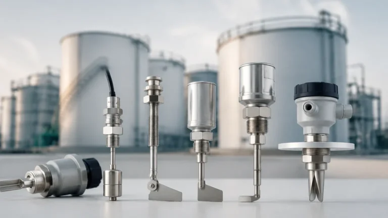
Before selecting a switch based on its electrical output, it is essential to determine which physical measurement principle is most suitable for the medium being monitored. Logic level switches utilize several different technologies to detect the presence or absence of a material at a specific point.
Vibrating Tuning Fork Switches
These switches utilize a piezoelectric crystal to vibrate a metal fork at its natural frequency. When the fork is immersed in a liquid or solid, the frequency changes or the vibration is dampened. The internal electronics detect this shift and toggle the logic state. This method is highly reliable for liquids and granulates as it is largely unaffected by flow, bubbles, or turbulence.
Float-Operated Reed Switches
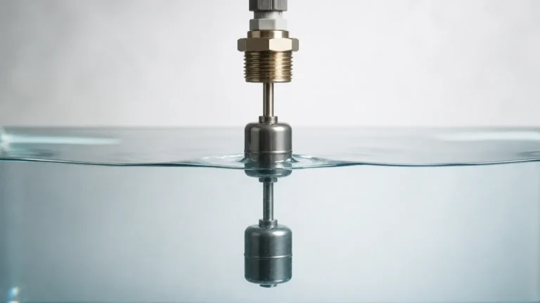
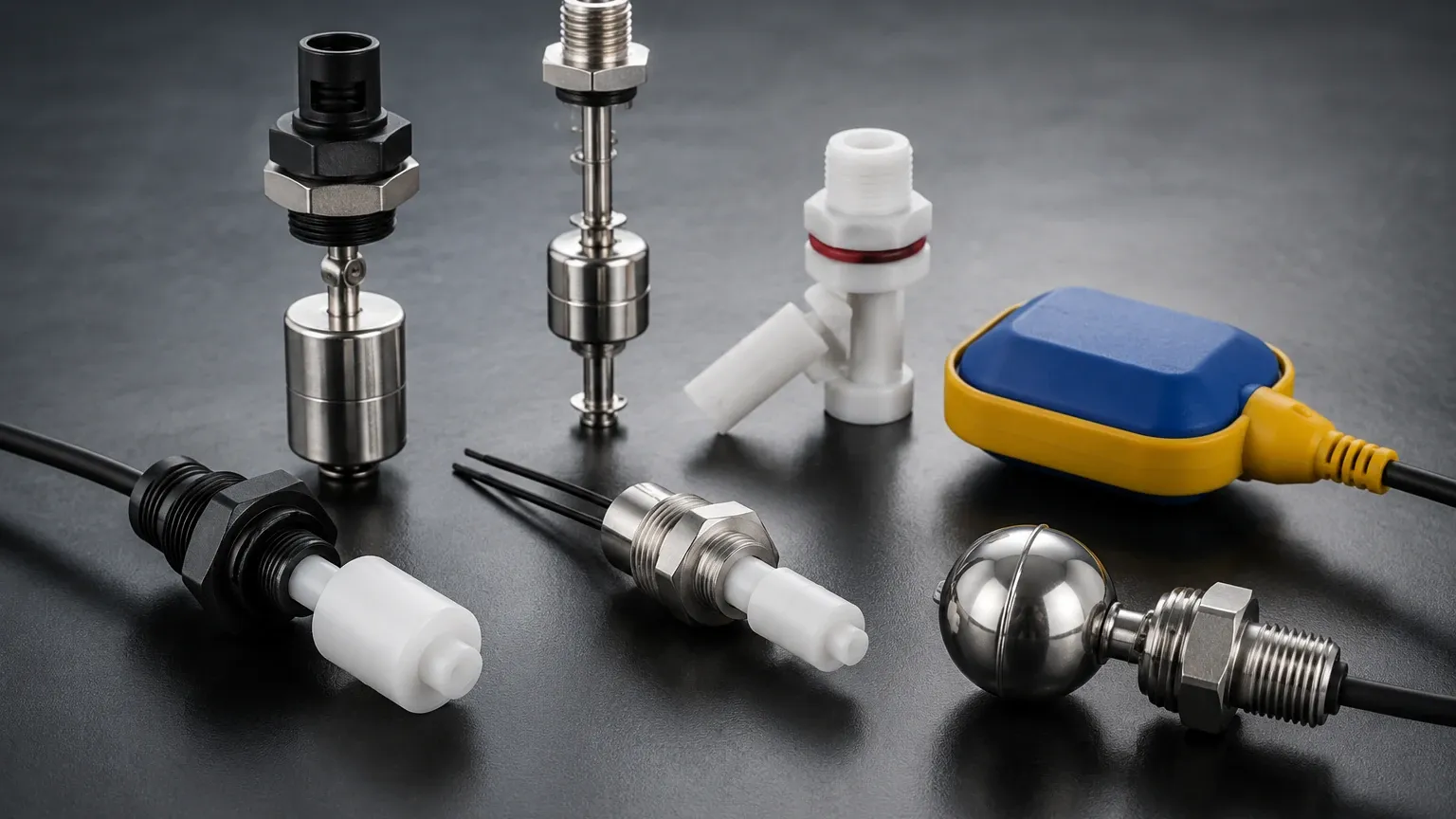
A magnetic float moves along a stem as the liquid level rises or falls. Inside the stem, a reed switch is hermetically sealed. When the magnet in the float reaches the reed switch, the contact closes or opens. Because reed switches can be manufactured with very low contact resistance, they are excellent for low-voltage logic circuits, provided the current is kept within the milliampere range to prevent contact welding.
Capacitive Level Switches
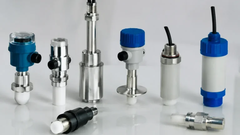
Capacitive sensors measure the change in capacitance between the sensor probe and the tank wall (or a reference electrode). As the medium displaces air, the dielectric constant changes, altering the capacitance. Logic-based capacitive switches are often used for non-contact sensing through plastic or glass vessel walls, making them ideal for high-purity or corrosive applications.
Ultrasonic Gap Switches
These devices consist of a pair of ultrasonic transducers separated by a small gap. When the gap is filled with liquid, the ultrasonic signal is transmitted from the sender to the receiver. When the gap is empty, the signal is attenuated. The electronics convert this transmission state into a logic-level output.
Electrical Interfaces: Sinking, Sourcing, and Voltage Levels
The term "logic level" refers to the electrical characteristics of the output signal. In industrial environments, the most common logic levels are 24V DC, though 5V (TTL) and 12V DC systems are still found in specialized or legacy equipment.
NPN (Sinking) vs. PNP (Sourcing)
This is a critical distinction for B2B procurement and engineering.
- PNP (Sourcing): The switch connects the output to the positive supply voltage (V+) when triggered. The PLC input must be a "sinking" type. PNP is the most common configuration in European industrial standards.
- NPN (Sinking): The switch connects the output to the common/ground (0V) when triggered. The PLC input must be a "sourcing" type. NPN is frequently used in Asian markets and in high-speed digital logic circuits.
Dry Contacts for Logic Circuits
While solid-state outputs (NPN/PNP) are preferred for high-speed switching and longevity, mechanical "dry" contacts (SPDT or DPDT) are used when complete electrical isolation is required. When using mechanical switches for logic levels, engineers must ensure the contacts are gold-plated or designed for "low-level" switching. Standard silver contacts require a minimum "wetting current" (often >100mA) to break through surface oxidation; logic circuits often operate at <10mA, which can lead to signal failure on standard contacts.
Practical Selection Table
The following table provides a comparison of common logic level switch technologies to assist in the initial selection phase.
| Technology | Suitable Media | Logic Output Types | Max Pressure | Temp Range | Key Advantage |
| :— | :— | :— | :— | :— | :— |
| Vibrating Fork | Liquids, Powders | PNP, NPN, Relay | 40 bar (4.0 MPa) | -40°C to 150°C | Foam & bubble immunity |
| Magnetic Float | Clean Liquids | Reed (Dry Contact) | 30 bar (3.0 MPa) | -20°C to 120°C | No power required at sensor |
| Capacitive | Liquids, Solids | PNP, NPN | 20 bar (2.0 MPa) | -40°C to 80°C | Non-contact through wall |
| Ultrasonic Gap | Non-aerated Liquids | PNP, NPN, Relay | 15 bar (1.5 MPa) | -30°C to 100°C | No calibration needed |
| Optical | Clear Liquids | PNP, NPN | 50 bar (5.0 MPa) | -20°C to 85°C | Extremely compact size |
Installation and Wiring Considerations
Proper installation is vital to ensure that logic level switches do not provide false triggers due to electrical noise or physical interference. Because logic signals operate at low voltages and currents, they are more susceptible to electromagnetic interference (EMI) than high-power circuits.
1. Cable Shielding: Always use shielded twisted-pair cabling for logic signals, especially if the cable run exceeds 10 meters. The shield should be grounded at the controller end only to prevent ground loops.
2. Signal Bounce: Mechanical logic level switches (like reed switches) can suffer from "contact bounce," where the signal oscillates rapidly for a few milliseconds during transition. Modern PLCs usually have software debouncing, but hardware RC filters may be necessary for high-speed counter inputs.
3. Mounting Orientation: For vibrating forks, ensure the forks are oriented so that material can flow through them rather than bridge across them. For float switches, ensure the mounting is perfectly vertical (within ±5°) to prevent the float from binding on the stem.
4. Proximity to Power Lines: Maintain a minimum clearance of 200mm (approx. 8 inches) between logic signal cables and high-voltage power cables (e.g., VFD outputs or motor leads) to prevent inductive coupling.
Limitations and Environmental Constraints
While logic level switches are highly effective, they have specific limitations that must be addressed during the design phase:
* Load Limits: A logic level output cannot drive a solenoid valve or a motor starter directly. Attempting to do so will likely destroy the output transistor (in NPN/PNP models) or weld the contacts (in reed models). An interposing relay must be used for power loads.
* Coating and Buildup: Capacitive and ultrasonic gap switches can be sensitive to material buildup. If the medium is viscous or prone to crystallization, a vibrating tuning fork with a "coating rejection" feature is a more robust choice.
* Dielectric Constant: Capacitive logic switches require a minimum dielectric constant (εr) to function. If the medium is a non-polar hydrocarbon with a very low dielectric constant, the sensitivity may need to be adjusted or a different technology selected.
Frequently Asked Questions (FAQs)
Can I use a 24V DC logic level switch with a 5V microcontroller?
Usually not directly. A 24V PNP signal will damage a 5V input. You must use a voltage divider, an optoisolator, or a logic-level shifter to step the signal down to the appropriate voltage.
What is the difference between "Normally Open" (NO) and "Normally Closed" (NC) in logic circuits?
In logic level switching, "Normally Open" means the output is in a high-impedance state (off) when the level is low. "Normally Closed" means the output is active (on) when the level is low. Most industrial switches allow you to select the logic polarity via wiring or a dip switch to suit the safety requirements of the application (e.g., fail-safe high or fail-safe low).
How do I troubleshoot a logic level switch that stays "ON" constantly?
First, check for material buildup on the sensor face. Second, verify the wiring—an NPN switch with a disconnected ground can sometimes appear as "high" depending on the PLC's internal pull-up resistors. Third, ensure the supply voltage is within the specified range (typically 10-30V DC); under-voltage can cause unpredictable logic states.
Are logic level switches suitable for hazardous areas?
Yes, but they must be used in conjunction with an intrinsically safe (IS) barrier. The barrier limits the energy sent to the switch in the hazardous area, ensuring that even in a fault condition, there is not enough energy to ignite an explosive atmosphere. The switch itself must be certified (e.g., ATEX, IECEx) for such use.
For engineers looking to integrate these components into their automation architecture, reviewing the specific electrical and chemical compatibility of the device is the first step toward a reliable installation. Detailed technical specifications and various sensor configurations can be found by exploring the range of Level Switches available for industrial applications.