Paddle Level Switches
Paddle Level Switches
In the landscape of industrial automation, the reliable detection of bulk solids within silos, hoppers, and bins is critical for preventing overflows, managing inventory, and protecting downstream equipment. Among the various technologies available, paddle level switches—also known as rotary paddle switches—remain a foundational solution due to their mechanical simplicity and robustness in harsh environments. These devices are a specific category of Level Switches designed to handle dry, granular, or powdered materials where non-contact sensors might struggle with dust or surface irregularities.
Understanding the Measurement Principle
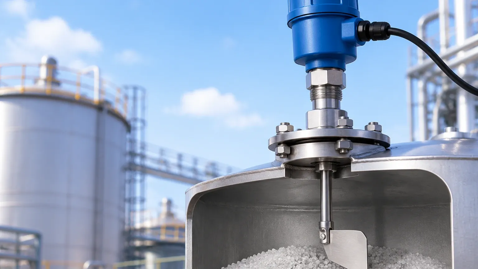
The operation of paddle level switches is based on a straightforward electromechanical principle. The device consists of a low-speed synchronous motor, a rotating shaft, and a paddle (or vane) extending into the vessel.
1. Free Rotation: When the material level is below the paddle, the motor rotates the shaft at a constant speed, typically around 1 to 5 revolutions per minute (RPM). During this phase, the internal microswitch remains in its "normal" state.
2. Material Contact: As the bulk material rises and reaches the paddle, it creates mechanical resistance. This resistance stalls the rotation of the paddle.
3. Torque Displacement: Because the motor continues to apply force, the motor housing itself (which is often mounted on a spring-loaded pivot) begins to rotate in the opposite direction of the stalled shaft.
4. Switch Activation: This displacement triggers one or more internal microswitches. The first switch typically cuts power to the motor to prevent overheating and mechanical wear, while the second switch provides the output signal (SPDT or DPDT) to the control system (PLC or alarm).
5. Reset: Once the material level drops and the paddle is no longer obstructed, the internal spring pulls the motor back to its original position, the microswitch resets, and the motor restarts rotation.
This mechanical approach makes the paddle level switch immune to changes in dielectric constants, humidity, or conductivity, which can often interfere with electronic sensors like capacitance or ultrasonic probes.
Key Components and Construction
To ensure longevity in industrial settings, paddle level switches are constructed from materials capable of withstanding abrasion and environmental stress.
* The Motor: High-quality synchronous motors are preferred for their ability to stall without immediate damage. Some advanced models include a "motor-off" feature when the paddle is stalled to extend the service life.
* The Housing: Usually made of die-cast aluminum or reinforced polymers, the housing must be rated for IP65 or IP66 to protect against dust and moisture ingress. In many bulk solid applications, such as flour milling or chemical processing, the housing must also meet ATEX or IECEx standards for dust-explosion protection.
* The Shaft and Seal: The shaft connects the motor to the paddle. A critical component is the shaft seal (often a triple-lip seal or a mechanical seal), which prevents fine powders from migrating into the motor housing.
* The Paddle: Paddles come in various shapes (scimitar, cross, or sickle) and materials (304 or 316 stainless steel). The choice of paddle depends on the density of the material being measured.
Technical Selection Criteria
Selecting the correct paddle level switch requires an analysis of the material properties and the physical environment of the vessel. The following table provides a general guideline for matching material density with paddle configurations.
| Material Density (kg/m³) | Recommended Paddle Type | Typical Materials |
| :— | :— | :— |
| < 100 kg/m³ | Large, multi-vane paddle | Perlite, sawdust, light plastic flakes |
| 100 – 500 kg/m³ | Standard 3-vane or sickle paddle | Grains, animal feed, plastic pellets |
| 500 – 1,500 kg/m³ | Heavy-duty 2-vane or scimitar paddle | Sand, cement, coal dust |
| > 1,500 kg/m³ | Reinforced scimitar or single-vane | Gravel, ore, heavy aggregates |
Material Density and Sensitivity
Sensitivity is often adjustable via a spring mechanism inside the housing. For very light materials, the spring tension is decreased so that even minimal resistance can stall the motor. For heavy materials, the tension is increased to prevent false trips caused by the weight of the material falling onto the paddle or the movement of heavy dust clouds.
Process Temperature and Pressure
Standard paddle switches typically handle temperatures up to 80°C. For high-temperature applications (up to 250°C or higher), extended shafts with heat sinks or ceramic insulators are required to protect the motor and electronics. Pressure ratings are generally low, often limited to 0.5 bar to 2 bar, though specialized high-pressure versions exist for pressurized conveying systems.
Installation and Engineering Best Practices
Proper installation is paramount to the reliability of paddle level switches. Incorrect placement can lead to mechanical failure or inaccurate readings.
1. Mounting Position:
* Top Mounting: Used for high-level detection. The switch is installed vertically through the top of the silo. If the silo is deep, a flexible cable extension is used instead of a rigid shaft to prevent the shaft from bending under the weight of material movement.
* Side Mounting: Used for high, mid, or low-level detection. The switch is installed horizontally through the side wall.
2. Protection from Material Flow: If the switch is installed near an inlet, a protective baffle or "shield" should be installed above the paddle. This prevents the direct impact of falling material from damaging the paddle or causing a false stall.
3. Cable Gland Orientation: When mounting horizontally, always ensure the cable glands point downward. This prevents moisture from following the cable into the housing via gravity.
4. Shaft Length: For side mounting, the paddle should extend at least 100 mm to 150 mm into the vessel to ensure it is clear of any material buildup on the vessel walls (the "dead zone").
Comparison with Alternative Point Level Technologies
While paddle level switches are highly effective, they are not the only option for point level detection. Engineers must weigh their benefits against other technologies like vibrating rods or capacitance switches.
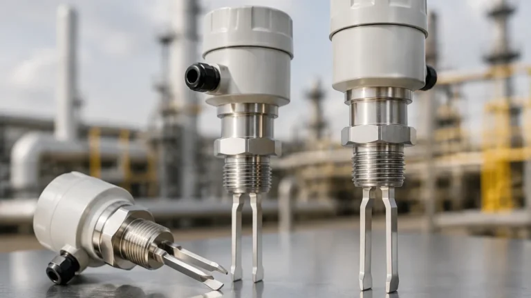
* Paddle vs. Vibrating Rod: Vibrating rods (tuning forks) have no moving parts, making them less prone to mechanical wear. However, they can be sensitive to material buildup (bridging) between the tines. Paddle switches are often preferred for very heavy or very light materials where vibration might be dampened or ineffective.
* Paddle vs. Capacitance: Capacitance switches are excellent for liquids and some solids but require calibration based on the material's dielectric constant. Paddle switches require no calibration for material changes, making them more "plug-and-play" for facilities that handle different types of bulk solids in the same silo.
* Paddle vs. Ultrasonic/Radar (Point): Non-contact point sensors are expensive and can be fooled by heavy dust or foam. Paddle switches provide a physical, mechanical confirmation of the material's presence, which is often more trusted in high-level alarm (overfill) safety circuits.
Limitations to Consider
Despite their versatility, paddle level switches have specific limitations:
* Mechanical Wear: Because they involve a motor and moving parts, they will eventually require maintenance or replacement, unlike solid-state sensors.
* Material Compatibility: They are not suitable for very sticky or adhesive materials that could coat the paddle and the housing, eventually seizing the shaft.
* Insertion Length: Rigid shafts are limited in length (typically up to 3 meters). For deeper requirements, cable extensions are necessary, but these can only be used for top-down mounting.
Maintenance and Troubleshooting
Maintenance for paddle level switches is generally minimal but should be performed annually in high-duty cycle applications.
* Visual Inspection: Check the paddle for signs of abrasion or bending. If the paddle is significantly worn, it may not provide enough surface area to stall the motor in light materials.
* Seal Integrity: Inspect the area where the shaft enters the housing. If powder is visible inside the housing, the shaft seal must be replaced immediately to prevent motor failure.
* Motor Test: Most modern units have a small viewing window or an LED indicator to show motor rotation. If the motor is not turning and there is no material obstruction, the motor unit likely needs replacement.
Common Troubleshooting Scenarios:
* False High Signal: Often caused by material "bridging" or sticking to the paddle. Increasing the spring tension or changing the paddle shape can help.
* No Signal when Full: This may occur if the material density is too low for the installed paddle. A larger paddle or a more sensitive spring setting is required.
* Motor Burnout: Usually a result of high-frequency cycling or excessive heat. Ensure the "motor-off" feature is functioning and that the ambient temperature at the housing is within specifications.
Frequently Asked Questions (FAQs)
Q: Can paddle level switches be used for liquids?
A: Generally, no. The resistance provided by most liquids is insufficient to stall the motor unless the liquid is extremely viscous (like heavy resins or sludges). For liquids, float switches or ultrasonic sensors are more appropriate.
Q: How do I choose between a rigid shaft and a wire rope extension?
A: Use a rigid shaft for side-mounting or for short top-mounting applications (under 1 meter). Use a wire rope extension for top-mounting in deep silos where the material's lateral force might bend a rigid shaft.
Q: Are paddle switches safe for use in food-grade applications?
A: Yes, provided the paddle and shaft are made of 316 stainless steel and the unit uses food-grade lubricants and seals. Many manufacturers offer specific models with FDA-compliant materials.
Q: What is the typical lifespan of a rotary paddle switch?
A: In a clean environment with moderate cycling, a high-quality paddle switch can last 5 to 10 years. In highly abrasive environments like cement or mining, the paddle may need replacement every 12 to 24 months.
For engineers and plant managers, the paddle level switch remains a reliable workhorse. Its ability to provide clear, mechanical feedback in the presence of dust, varying material densities, and changing environmental conditions ensures its continued relevance in the field of bulk solids management. When integrated correctly into a control strategy, these Level Switches provide a cost-effective and dependable safeguard for industrial process continuity.