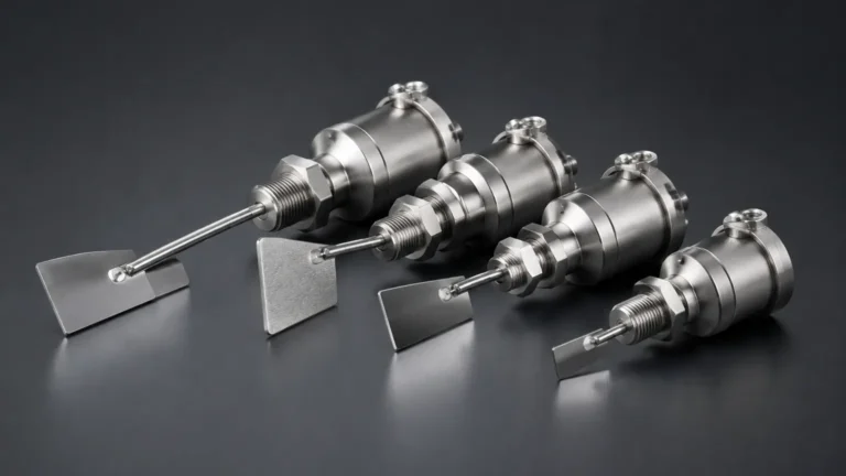
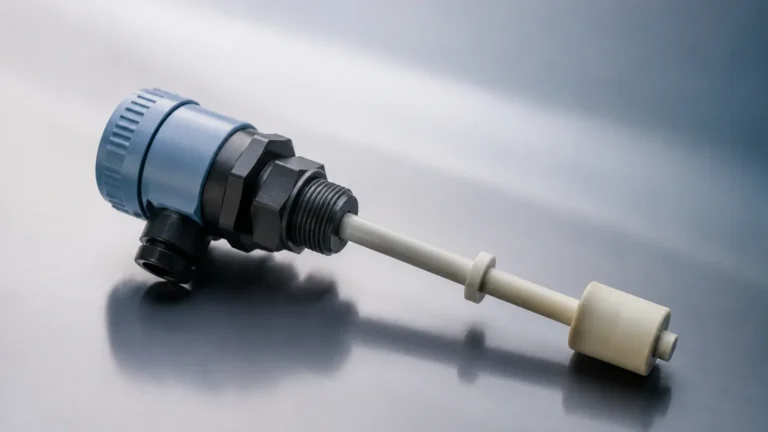
RF Level Switch 550 Connection Diagram
RF Level Switch 550 Connection Diagram
In the realm of industrial automation, point level detection serves as a critical safeguard for preventing tank overflows, protecting pumps from dry running, and managing inventory in silos. Among the various technologies available, Radio Frequency (RF) Admittance level switches are recognized for their versatility and reliability, particularly in environments where material buildup or coating on the probe is a concern.
Understanding the rf level switch 550 connection diagram and the underlying measurement principles is essential for electrical engineers and maintenance technicians to ensure accurate performance and system longevity. This guide provides a comprehensive technical overview of the RF 550 series, focusing on wiring configurations, installation best practices, and selection criteria for diverse industrial applications.
Understanding RF Admittance Measurement Principles
Before diving into the specific wiring and connection details, it is important to distinguish RF admittance technology from standard capacitance-based systems. While both utilize the dielectric properties of the medium, RF admittance is a more advanced evolution designed to overcome the limitations of material coating.
How it Works
An RF admittance level switch operates by applying a high-frequency radio signal (typically in the kilohertz or megahertz range) to a sensing probe. The instrument measures the "admittance"—the reciprocal of impedance—between the probe and the vessel wall (or a reference ground). Admittance consists of both capacitive and resistive components.
When the process material comes into contact with the probe, the electrical environment changes. The electronics detect this change in admittance and compare it against a preset threshold. If the change exceeds the threshold, the switch changes state (e.g., from "Normal" to "Alarm").
The "Shield" or "Guard" Section
The defining feature of the RF 550 series is the driven shield or guard section. This is a secondary conductive element on the probe that is energized at the same potential and frequency as the main sensing element. Because there is no potential difference between the shield and the sensor, no current flows between them. This effectively "ignores" any conductive material buildup on the probe insulation, ensuring the switch only triggers when the bulk material actually reaches the sensing tip. This makes Level Switches utilizing RF admittance ideal for sticky or viscous media.
RF Level Switch 550 Connection Diagram and Wiring
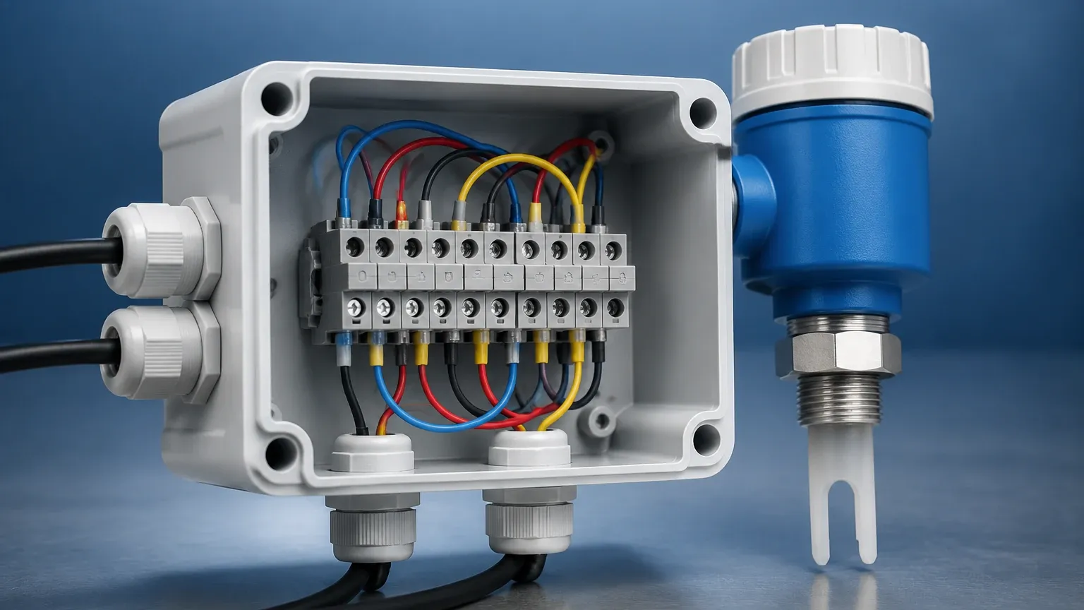
Correct electrical termination is the most critical step in the commissioning of an RF level switch. The rf level switch 550 connection diagram typically involves three main areas: the power supply, the signal output (relay), and the grounding circuit.
1. Power Supply Terminals
The RF 550 series is often designed with a universal power module or specific voltage variants.
* AC Power: Usually 220V AC or 110V AC (50/60 Hz). Terminals are typically marked L (Line) and N (Neutral).
* DC Power: Usually 24V DC. Terminals are marked + (Positive) and – (Negative/Common).
2. Relay Output (Signal)
Most RF 550 switches utilize a Double Pole Double Throw (DPDT) relay. This provides two sets of dry contacts that can be used to trigger alarms, stop motors, or interface with a PLC (Programmable Logic Controller).
* COM (Common): The moving part of the switch.
* NC (Normally Closed): Connected to COM when the switch is in the "Normal" state.
* NO (Normally Open): Connected to COM when the switch is in the "Alarm" state.
*Note: The definition of "Normal" and "Alarm" depends on the Fail-Safe setting (High or Low) selected on the internal DIP switches.*
3. Grounding and Shielding
For the RF circuit to complete, the instrument housing must be bonded to the vessel wall. If the tank is non-conductive (e.g., plastic or fiberglass), a reference ground rod or a large metal flange must be used. The grounding terminal inside the housing should be connected to a clean earth ground to prevent electrical noise from interfering with the high-frequency signal.
Wiring Summary Table
| Terminal Label | Function | Description |
| :— | :— | :— |
| L / + | Power (+) | 220V AC or 24V DC positive input |
| N / – | Power (-) | Neutral or 24V DC negative input |
| PE / GND | Earth Ground | Connection to vessel ground and safety earth |
| COM 1 / 2 | Relay Common | Common terminal for the DPDT output |
| NC 1 / 2 | Normally Closed | Contact closed in non-alarm state |
| NO 1 / 2 | Normally Open | Contact closed in alarm state |
Technical Selection and Application Criteria
Selecting the right configuration for an RF level switch 550 requires an analysis of the process media and the physical environment. The following table outlines standard selection parameters for common industrial scenarios.
| Application | Recommended Probe Type | Temperature Range | Pressure Limit |
| :— | :— | :— | :— |
| Water/Aqueous Liquids | Standard Stainless Steel / PFA | -40°C to 150°C | Up to 40 bar |
| Dry Powders (Cement/Flour) | Rigid Rod with Guard | -40°C to 200°C | Atmospheric |
| Corrosive Chemicals | Full PTFE/PFA Encapsulated | -40°C to 120°C | Up to 20 bar |
| High-Temp Fly Ash | Ceramic Insulated Rod | Up to 450°C | Atmospheric |
| Large Silos (Grains) | Flexible Cable Probe | -40°C to 80°C | High Tensile Load |
Key Evaluation Factors
1. Dielectric Constant (εr): Materials with higher dielectric constants (like water) are easier to detect than those with low constants (like dry hydrocarbons or plastic pellets).
2. Conductivity: Highly conductive materials require the driven shield feature to prevent false trips caused by moisture films.
3. Vibration: In high-vibration environments (e.g., near crushers), remote-mounted electronics are recommended to prevent damage to the PCB.
Installation Considerations
Proper physical installation is as important as the rf level switch 550 connection diagram. Errors in mounting can lead to mechanical failure or signal interference.
Mounting Orientation
* Top Mounting: Ideally suited for high-level alarms. The probe should be installed vertically, away from the fill stream to avoid false triggers or physical damage from falling material.
* Side Mounting: Common for low-level detection. The probe should be angled slightly downward (approx. 20 degrees) to allow liquid or moisture to drain off the probe surface.
Clearance and Obstructions
* Proximity to Walls: Maintain a minimum distance of 200mm (approx. 8 inches) from the tank wall to prevent capacitive coupling with the vessel structure.
* Internal Obstructions: Ensure the probe does not touch ladders, agitators, or baffles. For agitator tanks, the probe must be positioned in a zone of relatively calm material.
Cable Entry
Always install the instrument with the cable entries facing downward. Use a drip loop in the conduit to prevent moisture from traveling down the cable and entering the housing. For hazardous areas, ensure the use of certified explosion-proof cable glands.
Calibration and Sensitivity Adjustment
Once the wiring is complete according to the rf level switch 550 connection diagram, the unit must be calibrated to the specific medium.
1. Zero Adjustment: With the tank empty (material not touching the probe), turn the sensitivity potentiometer until the relay just switches, then back it off slightly. This accounts for the "base" capacitance of the probe and the empty tank.
2. Span/Sensitivity Adjustment: When the material covers the probe, verify the switch changes state. For low-dielectric materials, you may need to increase sensitivity (turn clockwise). For high-dielectric or sticky materials, decrease sensitivity to ensure the unit ignores the coating.
3. Time Delay: Most 550 models include a 0–30 second time delay. This is used to prevent "chatter" caused by surface turbulence or splashing.
Limitations and Common Risks
While RF admittance is robust, it is not infallible. Users should be aware of the following limitations:
* Extreme Coating: While the shield ignores thin coatings, an extremely thick, conductive "bridge" between the probe and the wall can still cause a false trip.
* Changing Dielectrics: If the process involves different fluids with widely varying dielectric constants, the switch may require recalibration between batches.
* Non-Metallic Tanks: In plastic tanks, the lack of a ground plane can lead to instability. A ground rod or metal plate must be installed to provide a reference point for the RF signal.
Frequently Asked Questions (FAQs)
Q: Can I cut the probe of an RF level switch 550 to a shorter length?
A: For rigid rod probes, shortening is usually possible, but it requires recalibration. However, cable probes must be ordered to the correct length, as the end weights and seals are factory-installed. Always consult the manufacturer's manual before modifying the probe.
Q: What is the difference between High-Level Fail-Safe (FSH) and Low-Level Fail-Safe (FSL)?
A: FSH means the relay is energized when the probe is uncovered; it de-energizes when material is detected or if power is lost (ideal for overflow prevention). FSL means the relay is energized when the probe is covered; it de-energizes when the tank is empty or power is lost (ideal for dry-run protection).
Q: Why does my switch trigger when the tank is empty?
A: This is often due to a lack of proper grounding or the sensitivity being set too high. Check the rf level switch 550 connection diagram to ensure the PE terminal is bonded to the tank, and perform a fresh zero-calibration.
Q: Is RF Admittance safe for food products?
A: Yes, provided the probe is specified with food-grade materials like 316L Stainless Steel and PFA/PTFE insulation that meets FDA requirements.
For engineers seeking reliable point level control, the RF 550 series offers a balance of advanced interference rejection and straightforward integration. By following the correct rf level switch 550 connection diagram and adhering to installation guidelines, facilities can achieve high-precision level monitoring even in the most challenging process conditions.