Level 7 Switch
Level 7 Switch
In the landscape of industrial automation and process control, the term "level 7 switch" often bridges the gap between physical instrumentation and high-level data architecture. While traditional level measurement focuses on the mechanical or electronic detection of a substance's height within a vessel, modern Industry 4.0 requirements demand that this data be accessible at the highest levels of the Open Systems Interconnection (OSI) model—specifically Layer 7, the Application Layer.
For engineers and plant managers, understanding how Level Switches function as the primary data source for these sophisticated networks is essential for optimizing safety, efficiency, and inventory management. This article explores the principles of point-level detection, the integration of these sensors into high-level control architectures, and the technical criteria for selecting the right equipment for demanding industrial environments.
Understanding Point Level Measurement Principles
Before discussing the integration into a level 7 switch or application-layer network, it is vital to understand the underlying physics of how level switches detect the presence or absence of material. Unlike continuous level transmitters that provide a constant 4-20mA or digital signal representing the exact level, a level switch acts as a high or low-limit alarm.
Vibrating Fork (Tuning Fork) Technology
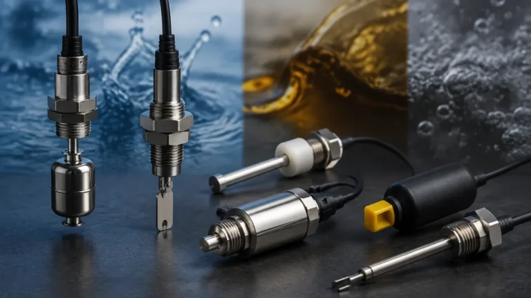
Vibrating fork switches utilize a piezo-electric crystal to energize a fork at its natural resonant frequency. When the fork is immersed in a liquid or solid, the frequency shifts or the amplitude of the vibration is dampened. The internal electronics detect this change and trigger a relay or transistor output. These are highly reliable for both liquids and granular solids because they are largely unaffected by flow, bubbles, or foam.
Float and Displacement Switches
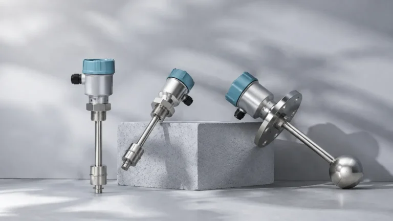
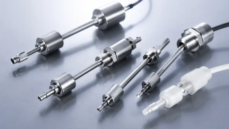
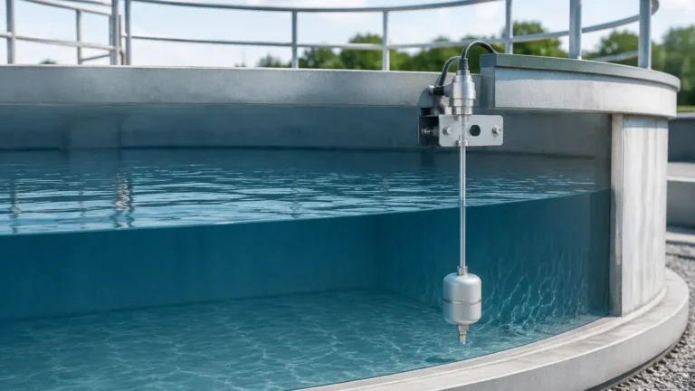
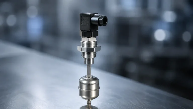
One of the oldest and most straightforward technologies, float switches rely on buoyancy. A float containing a magnet moves with the liquid level, actuating a reed switch or microswitch when it reaches a specific point. While simple, these are limited by mechanical wear and the potential for buildup on the moving parts.
Ultrasonic Level Switches
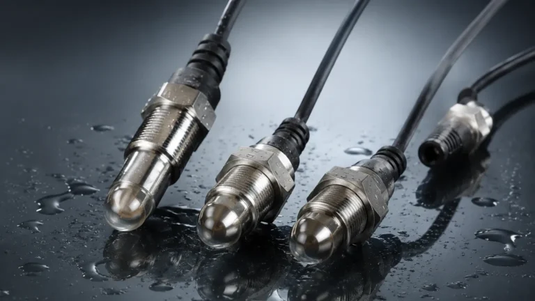
Ultrasonic point-level sensors use a pair of crystals (a transmitter and a receiver) separated by a gap. When the gap is filled with air, the ultrasonic signal cannot bridge the space efficiently. When liquid fills the gap, the signal passes through, signaling the electronics to change the switch state. This non-contact or gap-contact method is ideal for corrosive or high-viscosity fluids where mechanical floats might fail.
Capacitance Switches
Capacitance switches measure the change in electrical capacitance between a probe and the tank wall (or a second probe). Since different materials have different dielectric constants, the presence of a medium changes the capacitance of the circuit. These are versatile but require calibration based on the specific dielectric properties of the medium.
The Role of Level Switches in Industrial Automation Layers
In a modern facility, a level switch is no longer just a local alarm. It is a node in a complex data hierarchy. To understand the "Level 7" context, we must look at how the signal travels from the field to the enterprise level.
1. Layer 1 (Physical Layer): The physical sensor (e.g., a vibrating fork) detects the material.
2. Layer 2 (Data Link): The switch sends a signal via a protocol like IO-Link, Modbus, or a simple dry contact to a PLC (Programmable Logic Controller).
3. Layer 3-6: Data is routed through industrial gateways and switches, often involving IP addressing and session management.
4. Layer 7 (Application Layer): This is where the "level 7 switch" concept becomes relevant. At this stage, the data from the level switch is consumed by software applications such as SCADA (Supervisory Control and Data Acquisition), MES (Manufacturing Execution Systems), or ERP (Enterprise Resource Planning) software.
When a Level Switches unit is integrated into an IIoT (Industrial Internet of Things) framework, its status is visible globally, allowing for automated procurement (ordering more chemicals when a low-level switch is triggered) or predictive maintenance scheduling.
Technical Specifications and Selection Criteria
Selecting a level switch for a high-level integrated system requires more than just checking the pipe size. Engineers must evaluate the chemical, physical, and electrical requirements of the application.
| Feature | Vibrating Fork | Ultrasonic Gap | Float Switch | Capacitance |
| :— | :— | :— | :— | :— |
| Medium Type | Liquids/Solids | Liquids | Liquids | Liquids/Solids |
| Viscosity Limit | Up to 10,000 cP | Moderate | Low | High |
| Pressure Range | Up to 64 bar | Up to 40 bar | Up to 100 bar | Up to 100 bar |
| Temp. Range | -50°C to 150°C | -40°C to 100°C | -20°C to 200°C | -50°C to 250°C |
| Maintenance | Low | Low | Moderate | Moderate |
Media Density and Dielectric Constant
For float switches, the density of the liquid must be sufficient to provide buoyancy (typically >0.5 g/cm³). For capacitance switches, the dielectric constant (εr) must be significantly different from air (εr = 1). If the medium changes frequently, a vibrating fork is often a safer choice as it is density-independent above a certain threshold.
Process Conditions
High-pressure environments (e.g., boiler feed water) require robust housings and specialized seals. In the oil and gas industry, explosion-proof (Ex d) or intrinsically safe (Ex i) ratings are mandatory to prevent the switch from becoming an ignition source in hazardous atmospheres.
Integration with High-Level Control Systems
To achieve true level 7 switch connectivity, the output of the level sensor must be compatible with digital communication standards. Traditional switches provided a simple SPDT (Single Pole Double Throw) relay output. While functional, this provides no diagnostic information.
Modern Level Switches often feature:
* IO-Link: A short-distance, point-to-point digital communication protocol that allows the sensor to send its status, serial number, and internal temperature to a master node.
* HART (Highway Addressable Remote Transducer): Allows digital communication to be superimposed on a standard 4-20mA loop.
* WirelessHART / ISA100.11a: Enables level switches to be placed in remote locations without the cost of cabling, feeding data directly into the facility's mesh network.
By utilizing these protocols, a level switch moves from being a "dumb" device to a "smart" asset. It can report internal failures, such as crystal damage in a vibrating fork or coating on a capacitance probe, before a process failure occurs.

Installation and Maintenance Guidelines
Correct installation is the most critical factor in ensuring the longevity of a level switch. Even the most advanced sensor will fail if placed in an unsuitable location.
Mounting Positions
* Top Mounting: Standard for high-level alarms. Ensure the probe length is calculated correctly to account for the desired switching point.
* Side Mounting: Common for both high and low-level detection. For vibrating forks, the tines should be oriented so that material can easily flow through them, preventing "bridging" or false triggers.
* Avoid Turbulence: Do not install switches directly under a fill pipe. The turbulence and splashing can cause intermittent switching or mechanical damage.
Handling Turbulence and Foam
In tanks with agitators, use a stilling well to protect the sensor from lateral forces. For ultrasonic switches, heavy foam can absorb the signal, leading to false "empty" readings. In such cases, a vibrating fork or a heavy-duty float switch is often preferred.
Maintenance Checklists
1. Visual Inspection: Check for corrosion on the housing and buildup on the sensing element.
2. Function Test: Manually raise the level or use a test button (if equipped) to ensure the relay trips and the signal reaches the control room.
3. Seal Integrity: Inspect cable glands and conduit entries for moisture ingress, which is a leading cause of electronic failure in outdoor installations.
Common Challenges and Troubleshooting
Even with the best planning, process variables can change, leading to issues with level detection.
Issue: False High Alarms
* *Cause:* Material buildup or "clinging" on the probe. This is common with viscous liquids or sticky powders.
* *Solution:* Switch to a vibrating fork with a higher frequency or a capacitance switch with "active shield" technology that ignores coating.
Issue: Intermittent Signal
* *Cause:* Electrical noise or poor grounding. In a level 7 switch integrated environment, EMI (Electromagnetic Interference) from VFDs (Variable Frequency Drives) can corrupt digital signals.
* *Solution:* Use shielded twisted-pair cabling and ensure the instrument is properly grounded to the vessel.
Issue: Mechanical Failure of Floats
* *Cause:* Pressure spikes or particulate matter jamming the mechanism.
* *Solution:* Replace with a solid-state technology like an ultrasonic or vibrating level switch.
Summary for Project Engineering
Integrating a level switch into a modern industrial network requires a holistic view of the process. Whether you are managing a water treatment facility or a complex chemical refinery, the reliability of your Level Switches determines the accuracy of the data reaching your Level 7 application layer. By selecting the correct measurement principle and ensuring robust digital connectivity, you can transform simple point-level detection into a powerful tool for enterprise-wide optimization.
FAQ: Level Switches in Integrated Networks
Q: Can a level switch provide continuous level data?
No, a level switch is designed for point-level detection (on/off). For continuous measurement, a radar or ultrasonic level transmitter is required.
Q: What is the benefit of a digital output over a relay?
Digital outputs (like IO-Link) provide diagnostic data, such as sensor health and internal temperature, which allows for predictive maintenance and faster troubleshooting in a networked environment.
Q: Are level switches compatible with SIL (Safety Integrity Level) requirements?
Yes, many vibrating fork and ultrasonic switches are designed and certified for use in SIL 2 or SIL 3 loops, providing the high level of reliability required for overfill protection systems.