Fluid Line Products Inc
Fluid Line Products Inc
In the complex landscape of industrial process control, the term "fluid line products" encompasses a broad spectrum of components essential for the transport, regulation, and monitoring of liquids and gases. From high-pressure hydraulic fittings to specialized manifolds and valves, these components form the circulatory system of modern manufacturing. However, the efficiency of any fluid line is only as reliable as the instrumentation used to monitor it. For engineers and procurement specialists, understanding the synergy between fluid line products and advanced level measurement technology is critical for ensuring system integrity, safety, and operational efficiency.
This guide explores the technical requirements for integrating level measurement instruments into fluid line systems, focusing on the principles of operation, selection criteria, and practical installation considerations for industrial applications.
Core Measurement Principles for Fluid Line Applications
Before selecting instrumentation for fluid line products, it is essential to understand the underlying physics of level measurement. Industrial level sensors generally fall into two categories: contact and non-contact. Each principle offers distinct advantages depending on the fluid's properties and the environment of the fluid line.
Radar Level Measurement (FMCW and GWR)
Radar technology is widely regarded as the gold standard for precision in fluid lines. It operates on two primary principles:
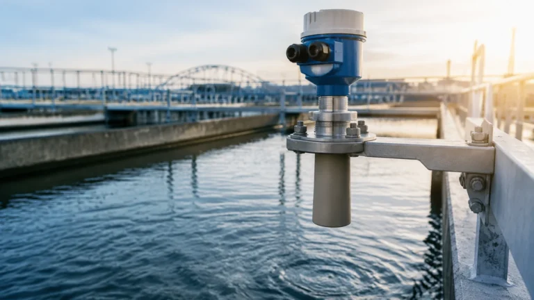
1. Non-Contact Radar (FMCW): Frequency Modulated Continuous Wave (FMCW) radar emits a high-frequency signal (typically 26 GHz or 80 GHz) toward the fluid surface. The instrument measures the frequency difference between the emitted and received signal to calculate the distance. This method is ideal for fluid lines containing corrosive chemicals or high-temperature liquids, as the sensor does not touch the media.
2. Guided Wave Radar (GWR): GWR utilizes a probe (rod or cable) that extends into the fluid. A low-energy pulse of microwaves is sent down the probe. When the pulse hits the fluid surface, the change in the dielectric constant causes a reflection. GWR is particularly effective in fluid lines with low dielectric fluids, foam, or turbulent surfaces.
Ultrasonic Level Measurement
Ultrasonic sensors function by emitting high-frequency sound waves. The sensor measures the "time-of-flight"—the duration it takes for the sound pulse to travel to the fluid surface and return. While cost-effective and reliable for water treatment and simple liquid storage, ultrasonic measurement is sensitive to environmental factors such as air temperature, pressure fluctuations, and heavy vapors within the fluid line.
Hydrostatic Pressure Measurement
Hydrostatic level transmitters measure the pressure exerted by a liquid column. Based on the principle that pressure at the bottom of a tank or pipe is proportional to the height of the liquid (P = ρgh), these sensors are highly effective for deep wells or pressurized fluid lines. They are typically installed at the lowest point of the system or submerged directly into the media.
Magnetic Level Gauges
Magnetic level gauges provide a visual indication of fluid levels by utilizing a float containing an internal magnet. As the fluid level in a bypass chamber (a specialized fluid line product) rises or falls, the float moves a series of bi-colored magnetic flaps. These systems are often paired with reed switches or transmitters for remote monitoring in high-pressure or high-temperature environments.
Key Selection Criteria for Level Sensors in Fluid Lines
Selecting the right instrument requires a detailed analysis of the fluid line's operating parameters. The following table provides a comparison of common technologies used in conjunction with fluid line products.
| Technology | Typical Accuracy | Pressure Range | Temp. Range | Media Compatibility |
| :— | :— | :— | :— | :— |
| 80GHz Radar | ±1 mm (0.04 in) | Up to 160 bar (2320 PSI) | -60°C to 250°C | All liquids, including corrosive |
| Guided Wave Radar | ±2 mm (0.08 in) | Up to 400 bar (5800 PSI) | -50°C to 450°C | Liquids and solids; low dielectric |
| Ultrasonic | ±0.25% of range | Up to 3 bar (43 PSI) | -40°C to 80°C | Water, wastewater, simple oils |
| Hydrostatic | ±0.1% to 0.5% | Dependent on depth | -20°C to 100°C | Homogeneous liquids |
| Magnetic Gauge | Visual + 5mm | Up to 320 bar (4640 PSI) | -196°C to 450°C | Clean liquids, toxic/flammable |
Fluid Characteristics
The chemical and physical properties of the media are the most important factors. For instance, if the fluid line carries highly corrosive acids, a non-contact radar with a PTFE-coated antenna is preferred. If the fluid is prone to foaming, Guided Wave Radar or a Magnetic Level Gauge is more reliable than ultrasonic or standard radar.
Process Conditions
Fluid lines in the oil and gas or chemical sectors often operate under extreme pressure and temperature. It is vital to ensure that the sensor's process connection (flange or thread) and housing material (typically 316L Stainless Steel) are rated for these conditions. For comprehensive technical specifications and to explore the full range of industrial sensors, engineers can visit the Main Page of our product catalog.
Integration of Fluid Line Components and Level Instrumentation
The physical integration of sensors into fluid line products requires specialized fittings and manifolds. Fluid line products such as bypass chambers, stilling wells, and standpipes are often used to isolate the sensor from turbulence or to provide a stable measurement environment.
1. Bypass Chambers: These are vertical pipes connected to the side of a tank or main fluid line. They allow for the installation of magnetic level gauges or GWR probes without requiring a top-down entry into the primary vessel.
2. Stilling Wells: In fluid lines where high agitation or surface ripples are present, a stilling well (a perforated pipe) can be used to dampen the fluid movement, ensuring a steady reading for ultrasonic or radar sensors.
3. Manifolds and Valves: High-quality valves are necessary to isolate level transmitters for maintenance or calibration without shutting down the entire fluid line system.

Installation Best Practices for Fluid Line Sensors
Proper installation is as important as the technology itself. Failure to follow engineering guidelines can lead to "dead zones," signal interference, or premature sensor failure.
* Avoid the "Dead Zone": Every sensor has a blocking distance (dead zone) near the antenna or transducer where measurement is impossible. Ensure the sensor is mounted high enough so the maximum fluid level never enters this zone.
* Mounting Position: Sensors should not be mounted directly above the fluid inlet. The turbulence and splashing from the incoming fluid will cause erratic readings. Ideally, the sensor should be placed at 1/4 to 1/6 of the tank diameter away from the wall.
* Nozzle Geometry: For radar and ultrasonic sensors, the mounting nozzle should be as short and wide as possible to prevent signal interference from the nozzle walls.
* Submersible Sensors: When using hydrostatic transmitters in deep fluid lines, ensure the cable is properly vented to the atmosphere to compensate for changes in barometric pressure.
Limitations and Maintenance of Fluid Line Measurement Systems
While modern instrumentation is highly advanced, there are inherent limitations to consider:
* Vapor and Condensation: Heavy steam or chemical vapors can attenuate ultrasonic signals. In such cases, high-frequency radar is a more robust choice.
* Build-up and Scaling: In fluid lines carrying wastewater or slurries, material can build up on the sensor face or probe. Regular inspection and the use of self-cleaning radar antennas or non-stick coatings can mitigate this risk.
* Dielectric Constant: Radar sensors rely on the dielectric constant (εr) of the fluid. If the εr is below 1.4, standard radar may struggle to receive a clear reflection, necessitating the use of Guided Wave Radar.
Maintenance should include periodic calibration checks against a manual reference (such as a dip tape) and cleaning of any submerged components. For digital transmitters, checking the signal strength (echo curve) via HART or Modbus communication can provide early warning of potential sensor fouling.
Frequently Asked Questions (FAQs)
Q: Can I use an ultrasonic sensor in a pressurized fluid line?
A: Generally, no. Ultrasonic sensors rely on the speed of sound, which changes with air density and pressure. For pressurized systems, radar or hydrostatic transmitters are significantly more accurate.
Q: What is the benefit of 80 GHz radar over 26 GHz radar?
A: 80 GHz radar has a much narrower beam angle. This allows it to be installed in smaller nozzles and prevents the signal from hitting internal obstructions like ladders or agitators in the fluid line.
Q: How do I measure the level of a fluid that is highly viscous or prone to clogging?
A: Non-contact radar is the best solution here, as there are no moving parts or probes in contact with the media. Alternatively, a flush-diaphragm hydrostatic transmitter can prevent material from becoming trapped in the sensor port.
Q: Are fluid line products from different manufacturers compatible with Welk sensors?
A: Yes, Welk instruments use standard industrial process connections (NPT/G threads, ANSI/DIN flanges), making them compatible with most high-quality fluid line products and manifolds available on the market.
Q: What is the maximum distance for a hydrostatic level transmitter?
A: Welk offers hydrostatic transmitters capable of measuring depths up to 500 meters (approx. 1640 feet), though most industrial fluid line applications fall within the 2 to 20-meter (6.5 to 65-foot) range.
By carefully matching the measurement principle to the specific requirements of the fluid line products in use, industrial operators can achieve a level of precision and reliability that minimizes waste and maximizes safety.