Flush Diaphragm Pressure Sensor
Flush Diaphragm Pressure Sensor
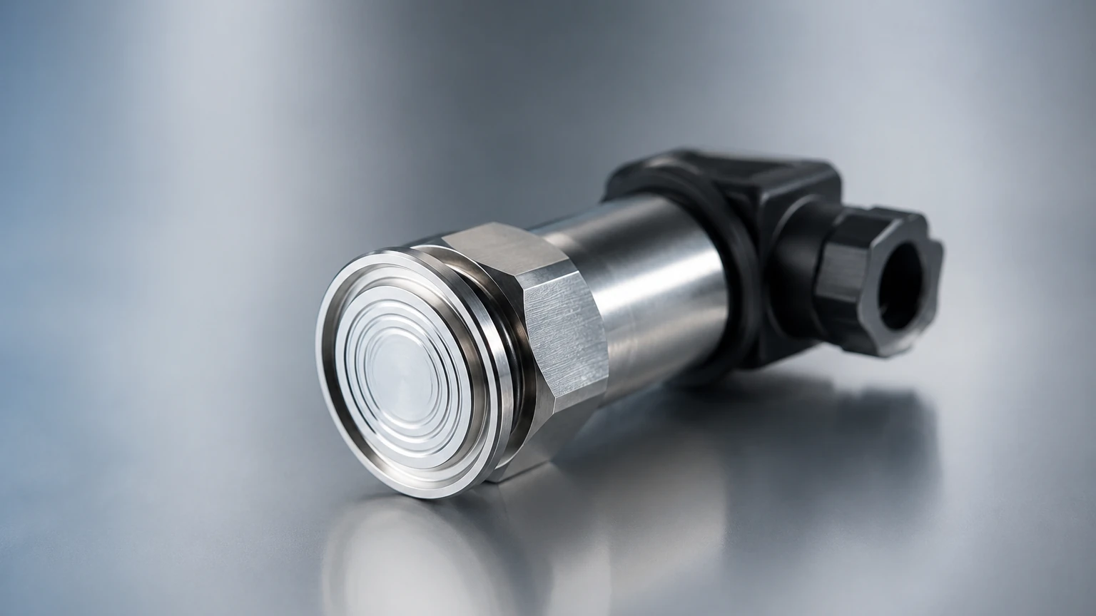
In industrial process control, the method by which pressure is transmitted to a sensing element determines the reliability of the measurement. A flush diaphragm pressure sensor is a specialized instrument designed to measure the pressure of media that would otherwise clog or damage a standard sensor. Unlike traditional pressure transmitters that utilize a small orifice or internal cavity to reach the sensing element, the flush design features a flat, exposed sensing surface. This configuration is essential for applications involving viscous fluids, slurries, or hygienic processes where material buildup must be prevented.
For engineers and system integrators, selecting the correct sensor architecture is critical for maintaining process uptime. This guide explores the engineering principles, application criteria, and technical considerations for implementing flush diaphragm technology in industrial environments. For a broader overview of available instrumentation and technical support, professionals can consult the Main Page of Welk’s product resource center.
Understanding the Measurement Principle
The fundamental operation of a flush diaphragm pressure sensor relies on the displacement of a metallic or ceramic membrane. When the process medium exerts force on the exposed diaphragm, the membrane deflects. This mechanical movement is then converted into an electrical signal through one of several sensing technologies.
Piezoresistive Sensing
Most flush diaphragm sensors utilize piezoresistive technology. In this design, a strain gauge is bonded to the internal side of the diaphragm or a secondary sensing element. As the diaphragm deflects, the resistance of the strain gauge changes proportionally to the applied pressure. This change is measured using a Wheatstone bridge circuit, which produces a voltage output that is subsequently conditioned into a standard industrial signal, such as 4-20mA or 0-10V.
Hydrostatic Level Measurement
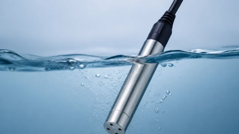
In the context of level measurement, these sensors function as hydrostatic transmitters. According to the principle of hydrostatics, the pressure at the bottom of a tank is directly proportional to the height of the liquid column (P = ρgh, where P is pressure, ρ is density, g is gravity, and h is height). By mounting a flush diaphragm sensor at the base of a vessel, the hydrostatic pressure can be used to calculate the exact liquid level. The flush face is particularly advantageous here as it prevents sediment from settling in a sensing port, which would otherwise lead to inaccurate "drift" in level readings.
Force Transmission and Fill Fluids
Because the sensing electronics are often isolated from the process for protection, many flush sensors use a "fill fluid" (typically silicone oil or food-grade oil) to transmit the force from the external diaphragm to the internal sensor chip. The integrity of this hydraulic link is vital; any air bubbles or leaks within the fill fluid will result in non-linear measurements and thermal instability.
Design and Construction Features
The construction of a flush diaphragm pressure sensor is dictated by the need for durability and chemical compatibility. Because the diaphragm is the only part in direct contact with the medium, its material and finish are the primary focus of engineering design.
Diaphragm Materials
* 316L Stainless Steel: The standard choice for most water treatment and general industrial applications due to its corrosion resistance and mechanical strength.
* Hastelloy C: Specified for highly corrosive chemical environments where stainless steel would suffer from pitting or stress corrosion cracking.
* Tantalum: Used for extremely aggressive acids.
* Ceramic: Offers superior abrasion resistance for slurries, though it may be more brittle than metallic options.
Process Connections
Flush sensors do not use standard NPT or G-thread internal ports. Instead, they utilize:
* Threaded Flush Mounts: Often G1/2" or G1" threads where the diaphragm sits flush with the end of the threaded bolt.
* Tri-Clamp Connections: Standard in the pharmaceutical and food industries (ISO 2852) to ensure a crevice-free hygienic seal.
* Flanged Connections: Used for large-scale tanks and high-pressure chemical reactors.
Key Applications in Process Industries
The choice to use a flush diaphragm pressure sensor is usually driven by the physical characteristics of the process media. Standard sensors with recessed diaphragms are prone to "plugging," where solids or high-viscosity liquids solidify within the pressure port, effectively isolating the sensor from the actual process pressure.
1. Food and Beverage Processing
In dairy and beverage production, hygiene is paramount. Standard pressure ports can trap bacteria or food particles, leading to contamination. Flush diaphragm sensors allow for Clean-in-Place (CIP) and Steam-in-Place (SIP) procedures, as the flat surface can be thoroughly sanitized by the flow of cleaning agents without disassembly.
2. Wastewater and Sewage Treatment
Wastewater often contains suspended solids, fibrous materials, and sludge. A flush diaphragm prevents these materials from clogging the sensor, ensuring reliable hydrostatic level monitoring in lift stations and primary clarifiers.
3. Pulp and Paper Industry
The high fiber content in paper pulp can quickly block traditional pressure transmitters. Flush sensors mounted on the side of pulp stock tanks provide continuous pressure and level data without the need for constant manual cleaning of the sensing ports.
4. Paints, Coatings, and Adhesives
Media that harden upon contact with air or over time are best measured with flush diaphragms. Since there is no cavity for the paint or adhesive to collect in, the risk of the sensor becoming permanently blocked is minimized.
Selection Criteria and Technical Specifications
When specifying a flush diaphragm pressure sensor, engineers must balance accuracy requirements with the environmental realities of the installation. The following table provides a comparison of key selection factors:
| Criteria | Specification Range | Engineering Consideration |
| :— | :— | :— |
| Pressure Range | 0-100 mbar to 0-600 bar | Ensure the range covers the maximum possible surge pressure. |
| Accuracy | 0.1%, 0.25%, or 0.5% FS | Higher accuracy is required for custody transfer or precise dosing. |
| Temperature Range | -40°C to +150°C (-40°F to 302°F) | High-temp versions require cooling fins or remote capillary seals. |
| Output Signal | 4-20mA, 0-10V, RS485, HART | HART protocol allows for remote calibration and diagnostics. |
| Material | 316L, Hastelloy, Ceramic | Must be chemically compatible with the process fluid. |
| Ingress Protection | IP65, IP67, IP68 | IP68 is required for submersible level applications. |
Thermal Effects and Compensation
Temperature changes affect the density of the internal fill fluid. This expansion or contraction can exert a small amount of pressure on the diaphragm, known as "temperature drift." High-quality sensors include internal temperature compensation circuits to nullify this effect, ensuring that a change in ambient or process temperature does not result in a false pressure reading.
Installation Considerations and Best Practices
Correct installation is as important as sensor selection. Even the most accurate flush diaphragm pressure sensor will fail if subjected to improper mechanical stress during mounting.
1. Avoid Diaphragm Contact: The diaphragm is extremely thin (often 0.05mm to 0.1mm). Any physical contact with tools or fingers during installation can dent the surface, permanently shifting the zero point or ruining the sensor.
2. Torque Specifications: Over-tightening a threaded flush sensor can cause "clamping stress," which deforms the housing and puts tension on the diaphragm. Always use a torque wrench and follow the manufacturer's specified limits.
3. Sealing Methods: For threaded versions, ensure the O-ring or gasket is compatible with the process fluid. In hygienic applications, the seal must be flush with the pipe wall to avoid creating dead spaces.
4. Orientation: While these sensors can generally be mounted in any orientation, mounting them on the side of a tank is preferred for level applications to prevent sediment from resting directly on the diaphragm surface over long periods.
5. Atmospheric Venting: For gauge pressure sensors, the cable or housing must have a vent path to the atmosphere. Ensure the vent tube is not kinked or blocked by moisture, as this will cause errors in measurement relative to atmospheric pressure.
Limitations and Potential Risks
While highly versatile, flush diaphragm sensors are not suitable for every environment. Engineers should be aware of the following limitations:
* Mechanical Fragility: The exposed nature of the diaphragm makes it vulnerable to damage from large debris or high-velocity particles in the flow stream. In such cases, a protective cage or a different measurement technology (like non-contact radar) may be necessary.
* Zero-Point Shift: Due to the internal fill fluid, these sensors are more sensitive to mounting position than recessed sensors. They typically require a "zero adjustment" after installation to account for the weight of the fill fluid in the specific mounting orientation.
* Abrasive Wear: Constant exposure to abrasive slurries can thin the diaphragm over time. While ceramic diaphragms mitigate this, they lack the flexibility and pressure range of metallic membranes.
* Vacuum Sensitivity: Some flush diaphragm designs are sensitive to vacuum conditions. If the process involves a vacuum, ensure the sensor is rated for "absolute" pressure or specifically designed to handle negative pressure without the diaphragm "ballooning" outward.
Frequently Asked Questions (FAQ)
Q: How do I clean a flush diaphragm sensor?
A: For most applications, the sensor is cleaned in place (CIP). If manual cleaning is required, use a soft cloth and a compatible solvent. Never use a wire brush or sharp object to scrape the diaphragm surface.
Q: Can a flush diaphragm sensor be used for steam applications?
A: Yes, but it must be rated for the specific temperature. Steam applications often require a "siphon" or a cooling neck to protect the electronics from extreme heat, even if the diaphragm can withstand the temperature.
Q: What is the difference between a flush diaphragm and a chemical seal?
A: A flush diaphragm sensor has the sensing membrane integrated directly into the transmitter body. A chemical seal (or remote seal) uses a capillary tube to connect a remote diaphragm to a standard pressure transmitter. Chemical seals are used when the transmitter needs to be mounted away from a high-temperature or vibrating process.
Q: How often should these sensors be calibrated?
A: In critical hygienic or chemical processes, annual calibration is standard. However, if the sensor is subjected to pressure spikes or extreme temperatures, more frequent zero-point checks are recommended.
Conclusion
The flush diaphragm pressure sensor is a vital component in the toolkit of process engineers dealing with challenging media. By eliminating the internal cavities found in standard sensors, these devices provide a reliable, hygienic, and clog-resistant solution for pressure and hydrostatic level measurement. Success in implementation depends on a thorough understanding of the media properties, careful material selection, and adherence to precise installation protocols.
For those evaluating instrumentation for new projects or seeking replacements for existing systems, reviewing technical specifications and application notes is the next logical step. Detailed product data and engineering support can be found by visiting the Main Page, where a full range of industrial level and pressure solutions is available to meet diverse operational requirements.