Non-invasive Flow Meters
Non-invasive Flow Meters
In modern industrial process control, the ability to measure fluid velocity and volumetric flow without breaching the integrity of the piping system is a significant operational advantage. Non-invasive flow meters, primarily utilizing ultrasonic technology, have become the standard for applications where system downtime, hygiene, or high-pressure safety are primary concerns. As a professional manufacturer of industrial measurement instruments, Welk provides these solutions to bridge the gap between high-precision requirements and the need for simplified installation.
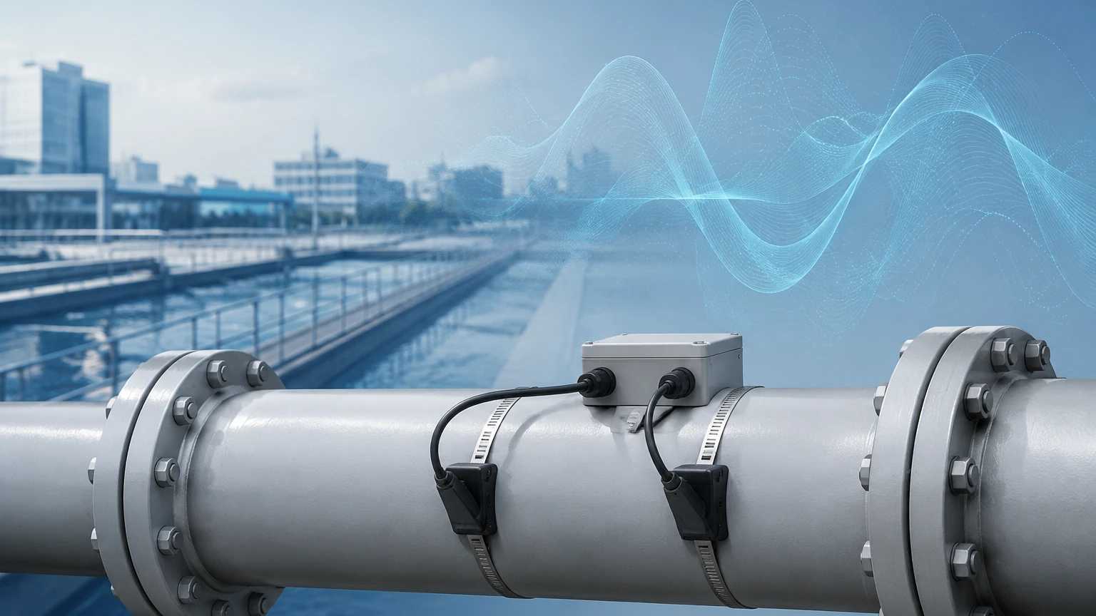
Unlike traditional electromagnetic or turbine meters that require cutting into the pipe and installing flanges, non-invasive flow meters—often referred to as clamp-on meters—attach to the exterior of the pipe. This guide explores the underlying principles, selection criteria, and practical installation requirements necessary for successful deployment in B2B industrial environments.
Understanding Non-invasive Flow Measurement Principles
To effectively select a non-invasive flow meter, engineers must first understand the two primary ultrasonic measurement principles: Transit-Time and Doppler. Both methods rely on the transmission of high-frequency sound waves through the pipe wall and into the fluid, but they are suited for different liquid characteristics.
Transit-Time Ultrasonic Technology
Transit-time measurement is the most common method for clean liquids. The system utilizes a pair of transducers (A and B) that act as both transmitters and receivers. Transducer A sends a signal to Transducer B (downstream), and then Transducer B sends a signal back to Transducer A (upstream).
When the fluid is stationary, the time taken for the signal to travel in both directions is identical. However, when the fluid is moving, the signal traveling downstream moves faster (assisted by the flow), while the signal traveling upstream moves slower (opposed by the flow). The flow meter measures this time difference (delta-T) with nanosecond precision. The velocity ($v$) is proportional to this time difference, and by knowing the cross-sectional area of the pipe, the volumetric flow rate can be calculated.
Ideal for: Potable water, demineralized water, chemicals, and light oils with less than 2% suspended solids or aeration.
Doppler Frequency Shift Technology
Doppler flow meters operate on the principle of frequency shift, similar to how a radar gun measures vehicle speed. A transducer transmits an ultrasonic signal of a known frequency into the pipe. This signal reflects off "discontinuities" in the fluid—such as suspended solids, grit, or entrained air bubbles.
Because these particles are moving at the same velocity as the fluid, the reflected signal returns to the transducer at a shifted frequency. The magnitude of this frequency shift is directly proportional to the velocity of the particles.
Ideal for: Slurries, wastewater, aerated liquids, and fluids with a high concentration of suspended solids (typically >100 ppm and particle sizes >75 microns).
Key Evaluation Criteria for Industrial Applications
Selecting a non-invasive flow meter requires a thorough assessment of the physical environment and the fluid properties. Failure to account for these variables often leads to signal loss or inaccurate readings.
1. Pipe Material and Condition
Non-invasive meters rely on the pipe wall being a good conductor of sound. Carbon steel, stainless steel, copper, and most plastics (PVC, PE, HDPE) are excellent candidates. However, pipes with internal liners (such as cement, bitumen, or rubber) present challenges because the acoustic impedance mismatch between the liner and the pipe wall can reflect the signal before it reaches the fluid. Furthermore, older pipes with internal scaling or heavy external corrosion must be prepared (sanded or ground) to ensure a flat, conductive surface for the transducers.
2. Fluid Temperature and Pressure
While the non-invasive nature means pressure is rarely a direct constraint on the sensor itself, temperature is critical. Standard transducers usually operate up to 80°C or 100°C. For high-temperature applications (e.g., thermal oil or steam condensate), specialized high-temperature transducers and high-viscosity coupling gels are required to prevent sensor degradation and signal drift.
3. Flow Profile and Reynolds Number
For accurate measurement, the flow profile must be fully developed and laminar or stable turbulent. This requires specific lengths of straight pipe run before and after the installation point. Generally, a minimum of 10 diameters (10D) upstream and 5 diameters (5D) downstream is recommended. If the installation is near a pump or a double-elbow, these requirements may increase to 25D or more.
Selection Table: Non-invasive vs. Inline Technologies
The following table provides a comparison to help engineering teams determine if a non-invasive approach is superior to traditional inline alternatives for their specific project.
| Feature | Non-invasive (Clamp-on) | Electromagnetic (Inline) | Vortex (Inline) |
| :— | :— | :— | :— |
| Installation | No pipe cutting; zero downtime | Requires pipe cutting and flanges | Requires pipe cutting and flanges |
| Pressure Drop | Zero | Zero (Full bore) | Moderate (Bluff body) |
| Maintenance | Low (No contact with fluid) | Moderate (Electrode cleaning) | Low (No moving parts) |
| Fluid Conductivity | Independent | Must be >5 μS/cm | Independent |
| Initial Cost | Higher for small pipes; Lower for large pipes | Linear with pipe size | Moderate |
| Accuracy | ±0.5% to ±2.0% of rate | ±0.25% to ±0.5% of rate | ±1.0% of rate |
| Typical Pipe Sizes | DN15 to DN6000 | DN3 to DN3000 | DN15 to DN300 |
Installation Guidelines and Best Practices
The performance of a non-invasive flow meter is 90% dependent on the quality of the installation. Even the most advanced electronics cannot compensate for a poorly mounted transducer.
Transducer Mounting Configurations
Depending on the pipe diameter and fluid attenuation, three primary mounting methods are used:
1. V-Method: The signals bounce off the opposite pipe wall once. This is the standard for pipes ranging from DN25 to DN400. It provides a good balance between signal strength and path length.
2. Z-Method: The transducers are mounted on opposite sides of the pipe. The signal crosses the pipe once. This is used for large-diameter pipes (DN500 and above) or where the fluid is highly attenuative, as it offers the shortest path and strongest signal.
3. W-Method: The signal bounces three times. This is reserved for very small pipes (below DN40) to increase the transit time and improve resolution.
The Role of Coupling Agents
Air is a poor conductor of high-frequency ultrasound. To ensure the signal passes from the transducer into the pipe, a coupling agent (acoustic gel or grease) must be applied. For permanent installations, solid epoxy or silicone-based couplants are preferred as they do not dry out over time. In portable survey applications, a standard petroleum jelly or specialized ultrasonic gel is sufficient.
Pipe Parameter Input
Before the meter can calculate flow, the user must input accurate pipe data into the transmitter. This includes:
* Outside diameter (OD)
* Wall thickness (measured via ultrasonic thickness gauge if unknown)
* Pipe material and liner material/thickness
* Fluid type (to determine the speed of sound in the liquid)
Limitations and Common Operational Risks
While non-invasive flow meters offer immense flexibility, they are not universal solutions. Engineers should be aware of the following risks:
* Signal Attenuation: In very large pipes or fluids with high concentrations of entrained air, the ultrasonic signal may be absorbed or scattered. If the signal strength falls below a certain threshold (typically 40-50 dB), the meter will fail to lock onto the flow.
* Pipe Wall Interference: If the pipe is made of a material with a sound speed very close to that of the liquid, "short-circuiting" can occur, where the signal travels through the pipe wall faster than through the fluid, leading to significant errors.
* Aeration and Cavitation: Non-invasive transit-time meters are highly sensitive to bubbles. If a pump is cavitating or if there is a leak in a suction line, the resulting air pockets will block the ultrasonic path.
Frequently Asked Questions (FAQ)
Q: Can non-invasive flow meters measure gas flow?
A: While most clamp-on meters are designed for liquids, specialized high-power ultrasonic meters exist for high-pressure gas applications. However, for standard low-pressure air or gas, non-invasive methods are generally not effective due to the low acoustic impedance of gases.
Q: How often does the coupling gel need to be replaced?
A: For permanent installations using high-quality silicone or solid coupling pads, the couplant can last 5 to 10 years. If using standard grease in a high-temperature environment, it should be inspected annually.
Q: Do non-invasive meters work on plastic pipes?
A: Yes, materials like PVC, PE, and HDPE are excellent for ultrasonic transmission. The only requirement is that the pipe must be full of liquid.
Q: Can these meters measure flow in partially filled pipes?
A: No. Transit-time and Doppler clamp-on meters require a full pipe to maintain the acoustic path. For partially filled pipes or open channels, different technologies like area-velocity radar or hydrostatic level transmitters are required.
Conclusion and Technical Support
Non-invasive flow meters represent a pinnacle of convenience in industrial instrumentation, allowing for rapid deployment and maintenance without process interruption. However, the accuracy of these devices is inextricably linked to the physical properties of the piping system and the precision of the installation.
For engineers looking to integrate these solutions into a broader automation strategy, it is essential to consult with a manufacturer that understands the nuances of acoustic physics and industrial environments. To explore a comprehensive range of level and flow measurement instruments, including radar, ultrasonic, and hydrostatic solutions, visit our Main Page for detailed product specifications and application support. Welk remains committed to providing the technical expertise required to ensure your measurement systems deliver reliable, long-term performance.