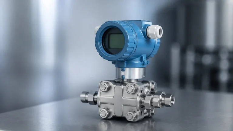
Starline 61 Sensor
Starline 61 Sensor
In the field of industrial process automation, the accuracy of level measurement directly impacts operational efficiency, safety, and inventory management. The Starline 61 sensor represents a significant advancement in non-contact level measurement technology, specifically utilizing high-frequency radar waves to determine the distance to a product surface. This technical guide examines the measurement principles, application criteria, and installation requirements for the Starline 61 sensor to assist engineers in selecting and deploying the technology effectively.
Measurement Principles of High-Frequency Radar
Before evaluating the specific capabilities of the Starline 61 sensor, it is essential to understand the underlying physics of Frequency Modulated Continuous Wave (FMCW) radar, which is the primary technology used in this class of instrumentation.
The FMCW Principle
Unlike traditional pulse radar, which measures the time-of-flight of a single microwave pulse, an FMCW radar sensor emits a continuous high-frequency signal. The frequency of this signal increases linearly over time, creating a "sweep" or a sawtooth wave pattern. When the signal reaches the surface of the medium, it is reflected back toward the sensor antenna.
By the time the reflected signal returns, the transmitter is already emitting a signal at a slightly higher frequency. The sensor’s internal electronics mix the transmitted and received signals, producing a "beat frequency" that is directly proportional to the distance. Because the frequency difference can be measured with extreme precision using Fast Fourier Transform (FFT) processing, FMCW sensors like the Starline 61 can achieve millimeter-level accuracy even over long distances.
Advantages of the 80GHz Frequency
The Starline 61 sensor typically operates in the 76 GHz to 81 GHz frequency range. This high frequency offers several distinct advantages over lower-frequency (e.g., 6 GHz or 26 GHz) radar systems:
1. Narrow Beam Angle: Higher frequencies allow for a much smaller antenna size while maintaining a narrow beam angle (often as low as 3°). This is critical for avoiding internal obstructions like agitators, ladders, or heating coils.
2. Increased Sensitivity: Shorter wavelengths are more easily reflected by materials with low dielectric constants (εr), such as plastic powders or certain oils.
3. Better Signal Separation: The high bandwidth of 80GHz technology allows the sensor to distinguish between the product surface and nearby interference, such as the bottom of a tank or buildup on the nozzle.
Technical Specifications and Evaluation Criteria
When specifying a Starline 61 sensor for a project, engineers must match the sensor's technical capabilities with the physical properties of the media and the vessel environment.
Key Performance Indicators
* Measurement Range: Most sensors in this category can measure up to 120 meters (approx. 393 feet), making them suitable for tall silos.
* Accuracy: Standard precision is typically ±2 mm, though some high-precision variants offer ±1 mm.
* Process Temperature: Standard units handle -40°C to +80°C, while specialized high-temperature versions can withstand up to +200°C.
* Process Pressure: Capabilities usually range from -0.1 MPa (vacuum) to 2.0 MPa (20 bar).
Selection Table: Radar vs. Alternative Technologies
| Feature | Starline 61 (80GHz Radar) | 26GHz Radar | Ultrasonic Sensor | Hydrostatic Transmitter |
| :— | :— | :— | :— | :— |
| Measurement Principle | FMCW Radar | Pulse Radar | Sound Waves | Pressure |
| Accuracy | ±2 mm | ±5 mm | ±0.25% of span | ±0.1% to ±0.5% |
| Beam Angle | 3° – 8° | 15° – 20° | 10° – 15° | N/A |
| Dust/Steam Resistance | Excellent | Good | Poor | N/A |
| Contact with Media | Non-contact | Non-contact | Non-contact | Contact required |
| Dielectric Dependency | Yes (εr > 1.4) | Yes (εr > 2.0) | No | No |
For a broader overview of how these technologies integrate into industrial systems, engineers can consult the Main Page of technical documentation for comparative analysis.
Application Suitability
The Starline 61 sensor is designed for versatility, but its performance is most pronounced in specific industrial scenarios.
Solids and Bulk Materials
In silos containing cement, grain, or plastic pellets, dust is a constant factor. Ultrasonic sensors often fail in these environments because the dust absorbs the sound waves. Radar waves, however, pass through dust with minimal attenuation. The narrow beam of the Starline 61 is particularly useful in narrow silos where wall reflections would otherwise interfere with the signal.
Corrosive and High-Purity Liquids
Because the sensor is non-contact, it is ideal for corrosive chemicals like acids or bases. The antenna can be shielded with PTFE (Teflon) or other resistant materials. In the food and pharmaceutical industries, the non-contact nature ensures that there is no risk of contamination from the sensor itself.
Narrow Tanks and Agitated Vessels
In tanks with internal structures, a wide radar beam will hit obstacles and return "false echoes." The 3° beam of the Starline 61 can be directed through narrow gaps between agitator blades and the tank wall, providing a clear reading of the liquid level even during active mixing.
Installation Considerations
Proper installation is the most critical factor in ensuring the long-term reliability of a Starline 61 sensor. Even the most advanced sensor will provide erratic data if mounted incorrectly.
Mounting Position
* Distance from Wall: The sensor should not be mounted too close to the vessel wall. A general rule is to maintain a distance of at least 200 mm from the wall to prevent the beam from reflecting off the side. However, it should also not be mounted directly in the center of a domed tank, as this can cause multiple reflections to converge at the sensor.
* Inlet Interference: Never install the sensor directly above the material inlet. The falling product will interfere with the radar signal and may cause buildup on the sensor face.
Nozzle Design
The nozzle (the pipe segment extending from the tank) must be designed to minimize interference. For 80GHz sensors, the nozzle should be as short as possible. If a long nozzle is required, the inner surface must be smooth and free of burrs or welds. The sensor's antenna should ideally extend slightly beyond the bottom of the nozzle to ensure the beam clears the opening without reflecting off the nozzle edges.
Alignment
For solids, the sensor may need to be aimed toward the discharge outlet or the angle of repose of the material. Specialized mounting flanges with aiming kits (swivel holders) allow the user to tilt the sensor to optimize the signal return from uneven surfaces.

Limitations and Common Risks
While the Starline 61 sensor is highly robust, engineers should be aware of specific conditions that can limit its performance.
1. Extremely Low Dielectric Constants: Materials like liquefied gases or certain dry powders with a dielectric constant (εr) below 1.4 may not reflect enough energy for a reliable signal. In these cases, a guided wave radar or a stilling well may be required.
2. Heavy Foam: While radar can penetrate some foam, thick, dense foam (like shaving cream consistency) can absorb or scatter the radar signal. If heavy foam is present, testing or the use of a different frequency may be necessary.
3. Condensation and Buildup: Although 80GHz radar is better at "seeing through" thin layers of buildup than lower frequencies, excessive moisture or material accumulation on the antenna face will eventually attenuate the signal. Air purging systems are recommended for applications with high humidity or sticky dust.
Frequently Asked Questions (FAQ)
Q: Can the Starline 61 sensor measure through a plastic tank lid?
A: Yes. Radar waves can penetrate non-conductive materials like plastic, fiberglass, or glass. This allows the sensor to be mounted outside the tank, which is useful for highly toxic or pressurized media.
Q: How does the sensor handle internal obstructions like ladders?
A: Most modern sensors include "False Echo Suppression" software. During commissioning, the user can perform a background scan of the empty tank. The sensor records the static reflections from ladders or pipes and ignores them during operation, focusing only on the moving surface of the product.
Q: Does the sensor require periodic calibration?
A: Unlike hydrostatic or ultrasonic sensors, radar sensors are generally drift-free because they rely on the constant speed of light. Periodic verification is recommended, but frequent recalibration is usually unnecessary unless the process conditions change significantly.
Q: What is the power requirement for these sensors?
A: Most Starline 61 sensors are 2-wire, loop-powered devices (4-20mA HART), operating on 24V DC. This simplifies wiring in industrial environments.
Conclusion
The Starline 61 sensor is a high-performance solution for complex level measurement challenges. By utilizing 80GHz FMCW technology, it provides the precision and narrow-beam focus required for modern industrial tanks and silos. When selecting a sensor, engineers must prioritize the dielectric properties of the media, the physical constraints of the vessel, and the potential for environmental interference. For additional technical specifications and to explore various level measurement configurations, please visit the Main Page for detailed product support.