Wastewater Lift Station
Wastewater Lift Station
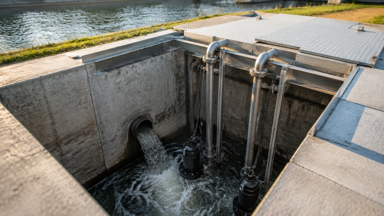
In municipal and industrial infrastructure, the wastewater lift station serves as a critical node for transporting effluent across varying elevations. Because gravity-fed sewer systems rely on a downward slope to move waste, lift stations—also known as pumping stations—are required when the terrain rises or when the distance to a treatment facility is too great for a continuous downward grade. These stations collect wastewater in a wet well and pump it to a higher elevation or into a pressurized force main.
Reliable operation of a wastewater lift station depends heavily on accurate level measurement. If the level sensing fails, pumps may run dry and burn out, or the wet well may overflow, leading to environmental contamination and significant regulatory fines. Choosing the correct instrumentation requires an understanding of the physics behind different measurement technologies and the specific challenges posed by the wastewater environment.
Measurement Principles for Lift Station Monitoring
Before selecting a sensor, engineers must understand the physical principles that govern how different instruments detect the liquid level in a wet well. In wastewater applications, the most common methods include ultrasonic, hydrostatic pressure, and radar technologies.
Ultrasonic Level Measurement (Non-Contact)
Ultrasonic sensors operate on the "Time-of-Flight" (ToF) principle. The transducer emits a high-frequency sound pulse that travels through the air, reflects off the liquid surface, and returns to the sensor. By measuring the time elapsed between transmission and reception, the device calculates the distance to the liquid.
* Formula: $Distance = (Speed of Sound \times Time) / 2$
* Advantage: Since the sensor never touches the wastewater, it is not subject to corrosion or fouling from solids and grease.
Hydrostatic Pressure Measurement (Contact)
Hydrostatic level transmitters are submersible sensors that sit at the bottom of the wet well. They measure the pressure exerted by the column of liquid above them. This pressure is directly proportional to the height of the liquid.
* Formula: $P = \rho \cdot g \cdot h$ (where $P$ is pressure, $\rho$ is liquid density, $g$ is gravity, and $h$ is height).
* Advantage: They are unaffected by surface foam, steam, or floating debris, which can sometimes interfere with non-contact sensors.
Radar Level Measurement (Non-Contact)
Radar sensors, particularly high-frequency 80GHz units, also use the Time-of-Flight principle but utilize electromagnetic waves instead of sound. These waves travel at the speed of light and are largely unaffected by air temperature, pressure, or the presence of heavy vapors.
* Advantage: Radar provides the highest precision and is the most resilient against environmental factors like wind, turbulence, and temperature fluctuations within the wet well.
Point Level Switches
While the above technologies provide continuous measurement (0–100%), float switches or conductivity probes are often used as redundant point-level indicators. These act as physical triggers for "High-High" or "Low-Low" alarms to prevent catastrophic failure if the primary transmitter fails.
Selection Criteria for Wastewater Environments
Selecting the right instrument for a wastewater lift station is not a one-size-fits-all process. Engineers must evaluate the specific characteristics of the wet well and the influent.
1. Presence of Foam and Grease: Thick layers of foam can absorb ultrasonic sound waves, leading to signal loss. In such cases, radar or hydrostatic sensors are preferred. Fats, Oils, and Grease (FOG) can coat submersible sensors, requiring frequent cleaning; therefore, non-contact radar is often the superior choice for high-FOG environments.
2. Turbulence and Inflow: If the influent pipe is located directly above the sensor, the resulting turbulence and splashing can cause erratic readings. Non-contact sensors with advanced signal processing (false echo suppression) can filter out these disturbances.
3. Chemical Composition: Wastewater often contains Hydrogen Sulfide ($H_2S$), which is highly corrosive. All exposed sensor components, including cables and housings, must be made of corrosion-resistant materials like PVDF, 316L Stainless Steel, or specialized elastomers.
4. Well Depth: For very deep wells (exceeding 15 meters or ~50 feet), the beam angle of ultrasonic and radar sensors becomes critical to avoid hitting the walls of the well or internal piping.
Practical Selection Table for Lift Station Sensors
| Technology | Best For | Limitations | Maintenance Level |
| :— | :— | :— | :— |
| Ultrasonic | Standard municipal wet wells; cost-effective projects. | Sensitive to heavy foam and steam. | Low (Non-contact) |
| Hydrostatic | Deep wells; wells with heavy surface foam or narrow spaces. | Susceptible to clogging from solids/grease. | Medium (Requires cleaning) |
| Radar (80GHz) | High-accuracy needs; heavy vapors; extreme turbulence. | Higher initial capital expenditure. | Very Low |
| Float Switches | Redundant backup; simple pump start/stop logic. | Prone to tangling and grease buildup. | High (Frequent inspection) |
For a comprehensive look at specific hardware configurations and technical data sheets, engineers can Review product options and application support to match these technologies to their specific site requirements.
Installation Guidelines and Best Practices
Proper installation is as important as the choice of technology. A poorly placed sensor will provide inaccurate data regardless of its quality.
Avoiding the Dead Zone
Every non-contact sensor (ultrasonic and radar) has a "dead zone" or "blocking distance" near the face of the transducer. If the wastewater rises into this zone, the sensor cannot provide a reading. Ensure the sensor is mounted high enough so that the maximum liquid level never enters this range (typically 0.25m to 0.5m depending on the model).
Positioning and Alignment
* Wall Interference: Mount the sensor away from the side walls. As a rule of thumb, the sensor should be placed at least 300mm (12 inches) away from the wall for every 3 meters (10 feet) of depth to prevent signal interference from the wall surface.
* Obstructions: Ensure the signal path is clear of ladders, pipes, and pump support cables. Modern radar sensors have narrow beam angles (e.g., 3 degrees), which makes it easier to avoid these obstacles.
* Hydrostatic Placement: Submersible pressure sensors should not be placed directly in the path of the influent or too close to the pump intake, where suction pressures can cause false readings. Using a stilling well (a perforated pipe) can protect the sensor from turbulence.
Cable Management
In wastewater lift stations, cables are exposed to moisture and corrosive gases. Use vented cables for hydrostatic sensors to compensate for atmospheric pressure changes, and ensure all cable entries are sealed with proper glands to prevent moisture ingress into the electronics housing.
Operational Limitations and Environmental Challenges
Even the most advanced systems face challenges in a wastewater lift station environment. Awareness of these limitations allows for better system design.
* Hydrogen Sulfide ($H_2S$) Gas: This gas is not only toxic but also highly corrosive to electronic circuits. Sensors used in lift stations should ideally have hermetically sealed electronics or be rated for hazardous areas (ATEX/IECEx) if the gas concentration is high.
* Temperature Gradients: Ultrasonic sensors rely on the speed of sound, which changes with air temperature. If the sun heats the top of the wet well while the wastewater remains cold, a temperature gradient is created. Sensors with integrated temperature compensation are mandatory for accuracy.
* FOG Buildup: Fats, oils, and grease are the primary cause of "ragging" and sensor failure. For hydrostatic sensors, a flush-diaphragm design is recommended to prevent grease from clogging the pressure port.
Frequently Asked Questions (FAQs)
Q: How often should I calibrate my lift station level sensor?
A: For non-contact sensors, an annual check is usually sufficient. Submersible hydrostatic sensors may require more frequent checks (every 3–6 months) to ensure the pressure port is not fouled by grease or silt.
Q: Can I use a radar sensor in a confined space?
A: Yes. Modern 80GHz radar sensors have a very narrow beam, making them ideal for narrow wet wells or tanks with internal obstructions that would interfere with wider ultrasonic beams.
Q: What is the benefit of a dual-sensor setup?
A: Many critical wastewater lift stations use a "primary/backup" configuration. For example, a radar sensor provides continuous level data to a SCADA system, while a high-level float switch provides a hard-wired emergency pump start or alarm signal. This redundancy is the industry standard for preventing overflows.
Q: Is it necessary to use explosion-proof sensors?
A: Depending on local regulations and the classification of the wet well (e.g., Class I, Div 1 or Zone 0), explosion-proof or intrinsically safe sensors are often required because of the potential for methane or other flammable gas accumulation in the sewer system.
By following these engineering principles and selection guidelines, operators can ensure that their wastewater lift station remains functional, efficient, and compliant with environmental safety standards. For detailed specifications on industrial-grade measurement tools, visiting the Main Page of a dedicated manufacturer provides the necessary technical depth for project planning.