Water Tank Level Sensors
Water Tank Level Sensors
In industrial automation and municipal water management, the precise monitoring of liquid inventory is a fundamental requirement for operational efficiency and safety. Water tank level sensors serve as the primary interface between physical storage and digital control systems, providing the data necessary to prevent overflows, manage pump cycles, and ensure a continuous supply for process requirements. Selecting the appropriate sensing technology requires an understanding of the physical principles governing measurement, as well as the specific environmental constraints of the application.
As a professional manufacturer, Welk provides a range of industrial-grade instrumentation designed to meet these challenges. For engineers and project managers evaluating their options, visiting the Main Page offers a technical overview of the hardware available for various liquid measurement scenarios.
Core Measurement Principles
Before selecting a sensor, it is essential to understand how different technologies interpret the "level" of water within a tank. Most industrial water tank level sensors fall into one of four categories: hydrostatic, ultrasonic, radar, or mechanical/magnetic.
Hydrostatic Pressure Measurement
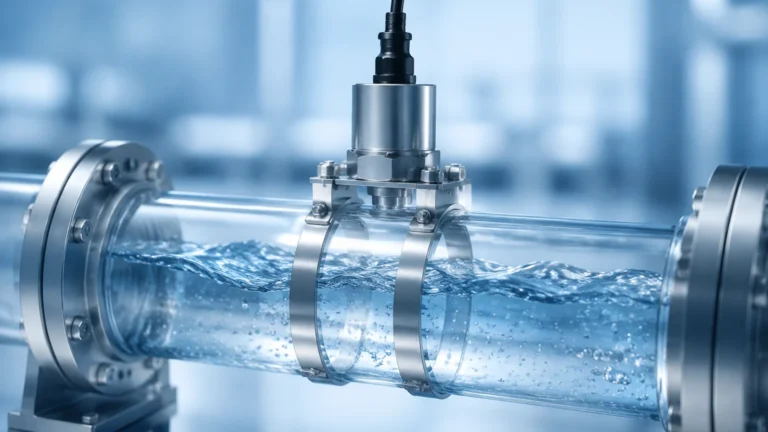
Hydrostatic level sensors operate on the principle that the pressure at a specific point in a static liquid is proportional to the height of the liquid column above it. This is expressed by the formula $P = \rho gh$, where $P$ is pressure, $\rho$ is the density of the liquid, $g$ is gravity, and $h$ is the height of the liquid.
In practice, a submersible pressure transmitter is lowered to the bottom of the tank. The sensor measures the weight of the water column and converts this into an electrical signal (typically 4-20mA). Because water density is relatively constant, these sensors provide highly reliable readings in deep tanks or reservoirs. However, they are "contact" sensors, meaning the probe is submerged in the media.
Ultrasonic (Time-of-Flight)
Ultrasonic sensors are non-contact devices that emit high-frequency sound pulses. These pulses travel through the air, bounce off the water surface, and return to the sensor. By measuring the time it takes for the pulse to return, the sensor calculates the distance to the water surface.
This technology is ideal for clean water applications where avoiding contact with the liquid is preferred to prevent contamination or sensor corrosion. However, ultrasonic waves can be affected by air temperature fluctuations, heavy foam on the water surface, or significant turbulence.
Radar Level Measurement
Radar sensors also use time-of-flight principles but utilize electromagnetic waves (microwaves) rather than sound. There are two primary types: non-contact radar and guided wave radar (GWR).
* Non-contact Radar: Emits a signal through the air. It is largely unaffected by temperature, pressure, or vacuum conditions, making it the gold standard for accuracy in challenging industrial environments.
* Guided Wave Radar: Uses a physical probe (cable or rod) to guide the microwave signal to the liquid surface. This is particularly effective in tanks with narrow geometries or where internal obstructions might interfere with a free-air signal.
Magnetic and Float-Based Systems
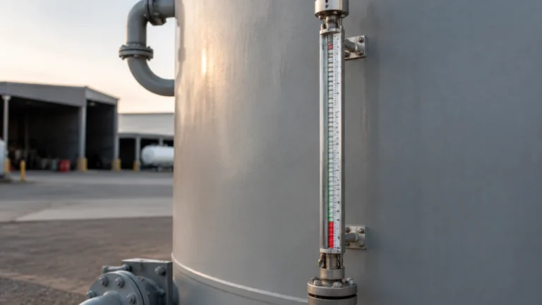
These are mechanical solutions where a float containing a magnet moves along a stem or bypass chamber. As the float rises and falls with the water level, it triggers reed switches or interacts with a magnetic display. While less sophisticated than radar, these systems are valued for their simplicity and the fact that they can provide a visual level indication without requiring external power.
Technical Selection Criteria
Choosing the right water tank level sensors involves balancing accuracy requirements against budget and installation constraints. The following table provides a comparison of the most common technologies used in industrial water management.
| Technology | Accuracy | Measurement Range | Typical Application | Advantages |
| :— | :— | :— | :— | :— |
| Hydrostatic | ±0.25% to ±0.5% | Up to 200m | Deep wells, large reservoirs | Simple installation, cost-effective for depth |
| Ultrasonic | ±0.25% of range | 0.3m – 15m | Open tanks, wastewater sumps | Non-contact, low maintenance |
| Radar (80GHz) | ±1mm to ±3mm | Up to 30m+ | Process water, chemical storage | Extremely high precision, ignores steam/foam |
| Guided Wave Radar | ±2mm | Up to 20m | Narrow tanks, turbulent surfaces | Not affected by tank geometry |
| Magnetic Gauge | ±5mm to ±10mm | 0.5m – 6m | Boiler feed water, visual monitoring | No power required for local display |
Practical Installation Considerations
The performance of water tank level sensors is often determined by the quality of the installation rather than the sensor's inherent specifications. Engineers should consider the following factors during the design phase:
1. Dead Zones (Blocking Distance)
Every non-contact sensor (ultrasonic and radar) has a "dead zone" or blocking distance directly beneath the sensor face where it cannot accurately measure. For example, if an ultrasonic sensor has a 300mm (approx. 12 inches) dead zone, the tank cannot be monitored accurately if the water level rises above that point. The sensor must be mounted high enough to account for the maximum expected fill level.
2. Mounting Location and Obstructions
Sensors should not be mounted directly above the water inlet, as the incoming flow will create turbulence and false readings. For radar and ultrasonic units, the "beam angle" must be considered. If the sensor is mounted too close to the tank wall or near internal ladders and pipes, the signal may reflect off these objects instead of the water surface.
3. Atmospheric Conditions
In outdoor water tanks, condensation can form on the sensor face. While many modern radar sensors are designed to "see through" light condensation, ultrasonic sensors may fail if water droplets block the transducer. In these cases, choosing a sensor with a PTFE (Teflon) face or a specialized aiming flange can mitigate the risk.
4. Stilling Wells
In tanks with high agitation or surface foam, a stilling well—a vertical pipe that acts as a buffer—can be installed. The sensor measures the level inside the pipe, which remains calm even if the rest of the tank is turbulent. This is a common requirement for guided wave radar and hydrostatic sensors in process water applications.
Limitations and Common Risks
While modern instrumentation is robust, there are specific risks that can lead to measurement drift or total signal loss:
* Build-up and Scaling: In hard water applications, calcium deposits can build up on hydrostatic diaphragms or ultrasonic transducers. Regular inspection and cleaning schedules are necessary to maintain accuracy.
* Signal Absorption: Heavy foam can absorb ultrasonic pulses, leading to a "lost echo" error. In such environments, high-frequency radar (80GHz) is generally the preferred alternative as it can penetrate foam layers more effectively.
* Pressure Variations: For hydrostatic sensors, if the tank is sealed and pressurized, the sensor will measure the air pressure plus the liquid pressure, leading to an incorrect level reading. In these instances, a differential pressure transmitter or a vented cable is required to compensate for the headspace pressure.
Frequently Asked Questions (FAQs)
Q: Can I use one sensor for both level measurement and pump control?
A: Yes. Most industrial sensors provide a 4-20mA signal that can be fed into a PLC (Programmable Logic Controller). Many also feature integrated relays that can be programmed to start or stop pumps at specific setpoints.
Q: What is the best sensor for a plastic (HDPE) water tank?
A: Radar is often the best choice because it can sometimes measure through the top of a plastic tank without requiring a hole to be cut, provided the plastic is not carbon-loaded or metallic-lined.
Q: How often do water tank level sensors need calibration?
A: Hydrostatic sensors should be checked annually for zero-drift. Ultrasonic and radar sensors are generally factory-calibrated and rarely require re-calibration unless the tank geometry or the dielectric constant of the liquid changes significantly.
Q: Is there a maximum depth for hydrostatic sensors?
A: Most industrial submersible sensors are rated for depths up to 100 or 200 meters (approx. 328 to 656 feet). For depths beyond this, specialized high-pressure housing is required.
Summary for Project Planning
When specifying water tank level sensors for a new project or a retrofit, it is critical to confirm the following data points before procurement:
1. Tank Dimensions: Total height, diameter, and the presence of internal obstructions.
2. Media Characteristics: Is it clean water, wastewater, or chemically treated process water?
3. Environmental Conditions: Operating temperature range and potential for vapor or foam.
4. Output Requirements: Does the system require a simple 4-20mA loop, Modbus, or wireless connectivity?
By matching the measurement principle to the specific constraints of the site, engineers can ensure long-term reliability and minimize maintenance overhead. For detailed product specifications and application support, professionals are encouraged to review the technical documentation available on the Main Page to find the most cost-effective and accurate solution for their specific industrial water management needs.