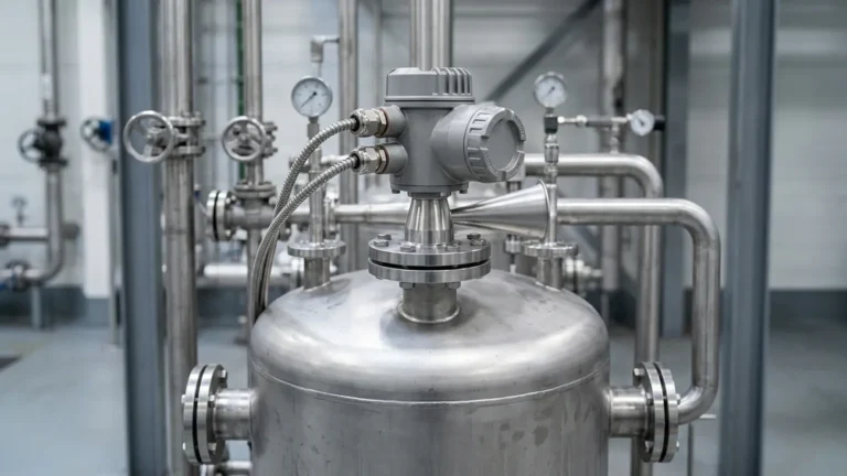
2 Level Transmitter
2 Level Transmitter
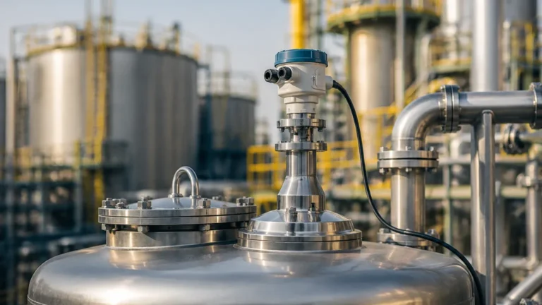
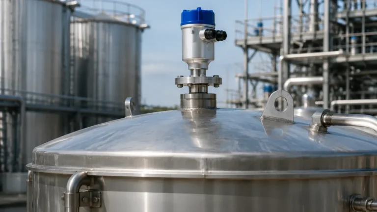
In the landscape of industrial process automation, the term 2 level transmitter typically refers to a 2-wire, loop-powered instrument designed to measure the distance, level, or volume of liquids and solids within a vessel. Unlike older 4-wire systems that require separate cables for power supply and signal output, the modern 2-wire configuration utilizes a single pair of wires to provide both the operating voltage (typically 24V DC) and the 4-20mA analog signal.
As industrial facilities strive for cost-efficiency and simplified wiring, Radar Level Meters have become the gold standard for 2-wire level measurement. This guide provides a technical deep-dive into the selection, installation, and application of these instruments to ensure reliable performance in demanding B2B environments.
Understanding the 2 Level Transmitter Configuration
The move toward 2-wire technology was driven by the need to reduce installation costs and simplify maintenance. In a 2-wire loop, the transmitter acts as a variable resistor. It regulates the current on the loop between 3.8mA and 20.5mA in direct proportion to the measured level.
The Role of HART Communication
Most high-performance 2-wire transmitters utilize the HART (Highway Addressable Remote Transducer) protocol. This allows digital data to be superimposed on the 4-20mA analog signal without interference. For an engineer, this means the 2 level transmitter can provide diagnostic data, sensor temperature, and signal strength alongside the primary level measurement, all through the same two wires.
Measurement Principles: Radar Technology in 2-Wire Systems
When selecting a 2 level transmitter, it is essential to understand the underlying physics of the measurement. Radar-based instruments generally employ one of two principles: Pulse Radar or Frequency Modulated Continuous Wave (FMCW).
1. Pulse Radar (Time of Flight)
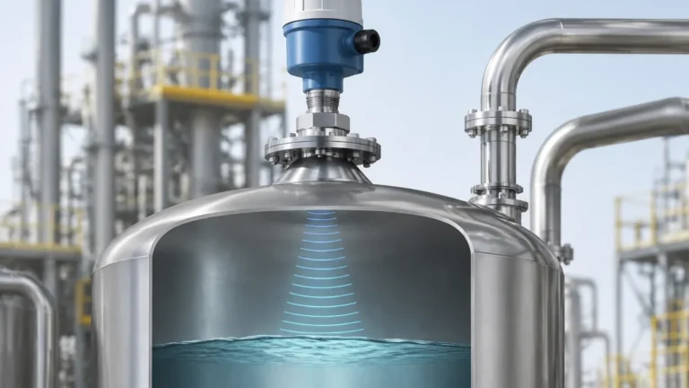
Pulse radar transmitters emit short microwave pulses toward the material surface. The instrument measures the time it takes for the pulse to travel to the surface and back to the sensor. Since the speed of light is constant, the distance is calculated as:
\[ D = \frac{c \times t}{2} \]
Where *c* is the speed of light and *t* is the measured time. Pulse radar is known for its low power consumption, making it ideal for standard 2-wire loop-powered applications.
2. FMCW (Frequency Modulated Continuous Wave)
FMCW radar emits a continuous signal with a constantly changing frequency. The difference in frequency between the emitted signal and the reflected signal is proportional to the distance. FMCW is generally more accurate and provides a better signal-to-noise ratio, which is critical when measuring materials with low dielectric constants or in tanks with internal obstructions.
Technical Selection Criteria for Industrial Applications
Choosing the right 2 level transmitter requires a detailed analysis of the process environment. The following table outlines the primary considerations for radar-based 2-wire transmitters.
Selection Table: Radar Technology Comparison
| Specification | 26 GHz Radar (K-Band) | 80 GHz Radar (W-Band) |
| :— | :— | :— |
| Beam Angle | 8° to 20° (Depends on antenna) | 3° to 8° (Highly focused) |
| Measurement Range | Up to 30m – 70m | Up to 120m |
| Accuracy | ±3 mm | ±1 mm |
| Process Connection | Threaded or Flanged (≥ 2") | Small threads (≥ 3/4") or Flanges |
| Best Use Case | Storage tanks, simple liquids | Narrow silos, agitated liquids, solids |
| Dielectric Constant (εr) | ≥ 1.9 | ≥ 1.4 |
Key Selection Factors
1. Frequency: Higher frequency (80 GHz) provides a narrower beam, which is essential for avoiding internal tank structures like ladders or agitators.
2. Dielectric Constant (DC): The reflectivity of the medium depends on its DC. Water has a high DC (~80), making it easy to measure. Hydrocarbons have low DCs (1.7 to 2.5), requiring more sensitive electronics.
3. Process Conditions: High temperatures (up to +250°C) and high pressures (up to 40 bar) require specialized antenna materials like PTFE or PEEK and robust housing materials like 316L stainless steel.
Installation Constraints and Best Practices
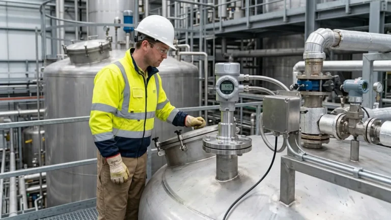
Even the most advanced 2 level transmitter will fail if installed incorrectly. Engineers must adhere to strict geometric constraints to ensure a clear signal path.
1. Nozzle Geometry
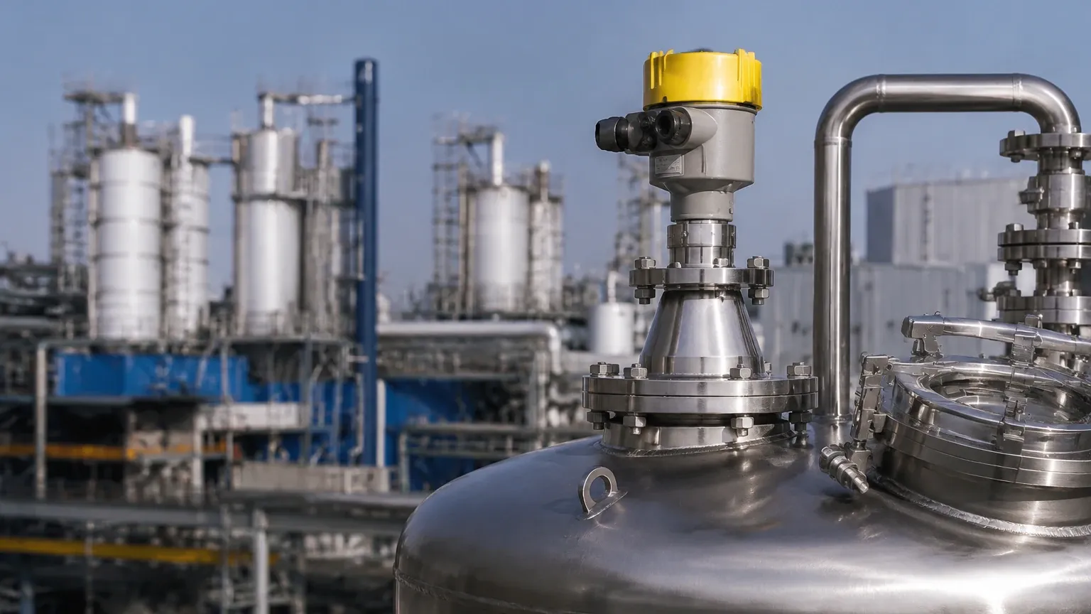
The nozzle height and diameter are critical. If the nozzle is too long or too narrow, the radar signal will reflect off the nozzle walls, creating a "ringing" effect that masks the actual level signal. Ideally, the antenna should extend slightly beyond the bottom of the nozzle.
2. Mounting Location
* Avoid the Center: Never mount a radar transmitter in the exact center of a domed-roof tank, as this can concentrate multiple reflections (parabolic effect) and lead to signal loss.
* The 1/6 Diameter Rule: A common rule of thumb is to mount the sensor at a distance of 1/6 of the tank diameter from the side wall.
* Inflow Interference: Ensure the radar beam does not intersect the path of the filling stream. Turbulence and air entrainment at the inflow point can cause signal scattering.
3. Obstruction Management
Internal structures such as heating coils, baffles, and ladders create false echoes. Modern Radar Level Meters include "False Echo Suppression" software, allowing the user to map out these static reflections so the transmitter ignores them.
Application Risks and Environmental Limitations
While 2-wire radar transmitters are highly versatile, certain environmental factors can pose risks to measurement accuracy:
* Heavy Foam: Dense, thick foam can absorb the radar signal entirely. In such cases, a guided wave radar (GWR) or a low-frequency radar might be more appropriate.
* Dust and Vapor: While 80 GHz radar penetrates dust well, extremely heavy steam or dust concentrations can attenuate the signal. Air purging systems are often used to keep the antenna lens clean.
* Condensation: Droplets on the antenna can cause signal drift. Choosing an antenna with a convex (drip-off) design helps mitigate this risk.
* Vacuum Conditions: Radar waves do not require a medium to travel, making them excellent for vacuum applications. However, the seal at the process connection must be rated for vacuum service to prevent instrument damage.
International Buyer Confirmation Checklist
When sourcing a 2 level transmitter from an international manufacturer, providing complete technical data is the only way to ensure equipment compatibility. Buyers should confirm the following before finalizing an order:
1. Medium Characteristics: Name of the medium, dielectric constant, and whether it is corrosive or abrasive.
2. Vessel Dimensions: Total height, diameter, and the presence of any internal obstructions.
3. Process Interface: Connection type (NPT/G thread or DIN/ANSI flange) and size.
4. Operating Environment: Minimum and maximum process temperature and pressure.
5. Output Requirements: Standard 4-20mA HART is typical, but check if Modbus RS485 or Profibus is required for your control system.
6. Certifications: Does the site require Explosion-proof (Ex d) or Intrinsically Safe (Ex ia) ratings? For water applications, are food-grade certifications needed?
Frequently Asked Questions (FAQ)
Q: Can a 2-wire transmitter be used in a 4-wire control system?
A: Yes, but you must use an external 24V DC power supply to power the loop. The signal is then read across a resistor in the circuit.
Q: What is the "Blind Zone" in a radar level meter?
A: The blind zone (or dead zone) is the area immediately below the antenna where the transmitter cannot accurately measure. This is usually between 50mm and 200mm, depending on the frequency and antenna design.
Q: How does a 2-wire transmitter handle power-intensive features like backlit displays?
A: Modern electronics are highly efficient. The instrument manages its power budget by prioritizing the measurement and signal output, often dimming the backlight or updating the local display less frequently than the internal measurement cycle.
Q: Is it necessary to empty the tank to calibrate the transmitter?
A: No. One of the primary advantages of radar-based Radar Level Meters is that they can be calibrated using the device’s software by entering the tank height and dielectric constant, without needing to change the actual fluid level.
Q: How long is the typical lifespan of a 2-wire radar level transmitter?
A: In non-corrosive environments with proper surge protection, these instruments often last 10 to 15 years. The lack of moving parts significantly reduces wear and tear compared to mechanical level gauges.
By carefully considering these technical factors, engineers can successfully implement a 2 level transmitter solution that provides accurate, maintenance-free data for years to come, even in the most challenging industrial environments.