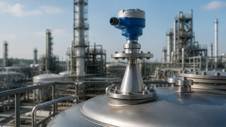
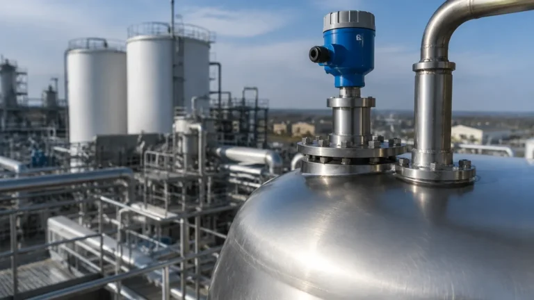
Lr250 Radar Level Transmitter
LR250 Radar Level Transmitter: A Technical Guide to High-Frequency Level Measurement
In the landscape of industrial automation, accurate level measurement is critical for inventory management, process safety, and operational efficiency. Among the various technologies available, the lr250 radar level transmitter has established itself as a standard for non-contact measurement in liquid and slurry applications. Operating at a high frequency of 25 GHz, this class of transmitter offers a narrow beamwidth and high sensitivity, making it suitable for small vessels and complex internal geometries.
This guide provides an engineering overview of the technology behind the lr250 radar level transmitter, its selection criteria, installation requirements, and the practical considerations necessary for successful deployment in industrial environments.
Measurement Principles: FMCW and High-Frequency Radar
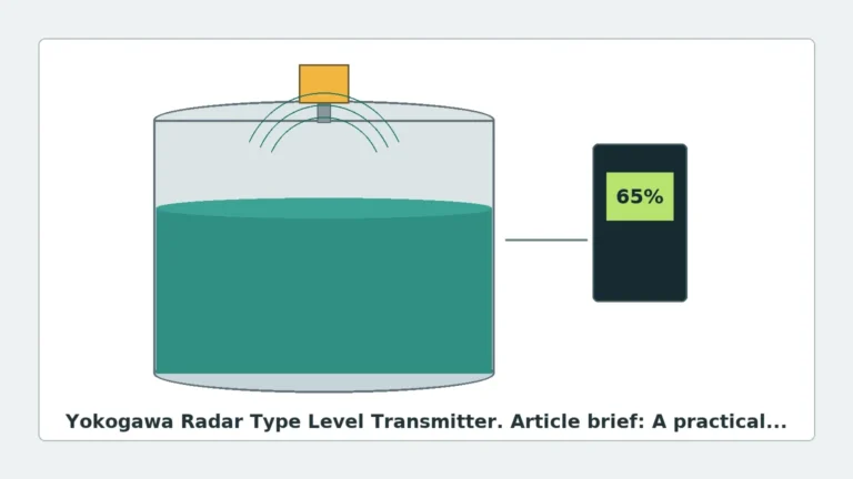
Before selecting a specific instrument, it is essential to understand how Radar Level Meters operate. The lr250 radar level transmitter typically utilizes Frequency Modulated Continuous Wave (FMCW) technology or high-frequency pulsed radar.
Frequency Modulated Continuous Wave (FMCW)
In FMCW systems, the transmitter emits a continuous signal with a constantly changing frequency. When the signal reflects off the material surface and returns to the antenna, the frequency of the received signal is compared to the frequency of the signal being emitted at that moment. The difference between these frequencies ($Δf$) is directly proportional to the time of flight, allowing the device to calculate the distance to the material surface with high precision.
The 25 GHz Advantage
The 25 GHz operating frequency is a significant factor in the performance of the lr250 radar level transmitter. Compared to lower frequency radars (such as 6 GHz units), the 25 GHz signal has a shorter wavelength, which results in several technical benefits:
1. Narrower Beamwidth: A 25 GHz signal can be focused into a tighter beam using a smaller antenna. This is crucial in tanks with internal obstructions like agitators, ladders, or heating coils.
2. Higher Sensitivity: Shorter wavelengths reflect more effectively off turbulent surfaces or materials with lower dielectric constants.
3. Smaller Form Factor: The ability to use smaller horn antennas allows for installation on smaller nozzles, often as small as 50 mm (2 inches).
Technical Specifications and Features
The lr250 radar level transmitter is designed as a 2-wire, loop-powered instrument, which simplifies wiring and integration into existing control systems via 4-20 mA HART, PROFIBUS PA, or FOUNDATION Fieldbus protocols.
Signal Processing and Process Intelligence
Modern transmitters in this category utilize advanced signal processing algorithms, often referred to as "Process Intelligence." This software filters out false echoes generated by tank walls, weld seams, or internal obstructions. By maintaining a dynamic "echo profile," the transmitter can track the actual level even in the presence of background noise or changing process conditions.
Antenna Configurations
Selection of the correct antenna is vital for application success. Common options include:
* Horn Antennas: Available in various sizes (typically 1.5", 2", 3", and 4"). Larger horns provide a narrower beam and better signal strength.
* PVDF Encapsulated Antennas: Used for highly corrosive chemicals where metallic components would be degraded.
* Flanged Versions: For high-pressure or high-temperature applications where a secure process connection is mandatory.
Selection Criteria for Industrial Applications
When specifying an lr250 radar level transmitter, engineers must evaluate the physical and chemical properties of the media, as well as the vessel geometry. The following table provides a general selection framework for different process conditions.
Selection Table: Radar Configuration vs. Application
| Application Feature | Recommended Configuration | Rationale |
| :— | :— | :— |
| Corrosive Acids/Bases | PVDF Encapsulated Antenna | Provides chemical resistance and prevents metallic contamination. |
| Small Vessels (< 3m) | 25 GHz Horn (Threaded) | Narrow beam avoids wall interference in tight spaces. |
| High Turbulence | Large Horn Antenna (4") | Increased signal-to-noise ratio helps track moving surfaces. |
| Hygienic/Food Grade | Stainless Steel with Triclamp | Meets sanitary requirements and allows for CIP (Clean-in-Place). |
| Solids/Powders | Aiming Flange + Dust Shield | Allows the beam to be angled toward the material's angle of repose. |
Installation Considerations
Correct installation is the most critical factor in ensuring the reliability of an lr250 radar level transmitter. Even the most advanced Radar Level Meters will fail if positioned incorrectly.
1. Nozzle Positioning
The transmitter should be located approximately 1/3 of the tank diameter away from the side wall. Placing the unit too close to the wall will result in parasitic reflections, while placing it in the exact center may lead to interference from the "vortex" created during filling or emptying.
2. Nozzle Height and Diameter
The antenna must extend past the bottom of the mounting nozzle. If the horn is recessed within the nozzle, the signal will reflect off the nozzle walls, creating a large "dead zone" or "near-blanking" area at the top of the tank. For standard horn antennas, the nozzle height should be kept as short as possible.
3. Avoiding Obstructions
The radar beam is conical. Any metal object within this cone (agitator blades, pipes, ladders) will reflect the signal. While signal processing can "mask" these objects, it is best practice to provide a clear line of sight to the material surface.
4. Environmental Protection
In outdoor installations, a sunshade is recommended to prevent electronic drift caused by extreme temperature fluctuations. Additionally, ensure the cable glands are pointed downward to prevent moisture ingress into the housing.

Limitations and Application Risks
While the lr250 radar level transmitter is highly versatile, certain conditions can challenge its accuracy:
* Dielectric Constant (εr): Radar relies on the difference in dielectric constants between the air and the medium. Materials with very low dielectrics (e.g., liquefied gases or certain hydrocarbons with εr < 1.6) reflect very little energy. In these cases, a guided wave radar or a larger antenna may be required.
* Heavy Foam: Dense, thick foam can absorb the radar signal rather than reflecting it. If the foam is light and airy, the radar may see through it to the liquid; however, thick chemical foams often require alternative technologies like ultrasonic or hydrostatic sensors.
* Vacuum and Pressure: While radar works well in a vacuum (unlike ultrasonic sensors), extreme pressures can affect the dielectric constant of the vapor space, requiring compensation in the transmitter settings.
Commissioning and Maintenance
Commissioning an lr250 radar level transmitter involves setting the "Mapping" or "TVT" (Time Varying Threshold) curve. This process involves recording the echo profile of an empty or partially empty tank so the transmitter can identify and ignore static reflections from internal structures.
Maintenance Checklist:
1. Antenna Inspection: Check for buildup of material or condensation on the antenna lens. While many 25 GHz units handle thin films well, heavy buildup will attenuate the signal.
2. Seal Integrity: Inspect the process seal and O-rings, especially in high-temperature or corrosive applications.
3. Loop Diagnostics: Verify that the 4-20 mA signal matches the digital reading on the local display to ensure there is no loop resistance interference.
Frequently Asked Questions (FAQ)
Q: Can the lr250 radar level transmitter measure solids?
A: Yes, but with caveats. While primarily designed for liquids, it can measure small-grain solids in smaller silos. For large silos with significant dust, a specialized solids radar with a higher power output or an aiming flange is usually preferred.
Q: How does condensation affect the measurement?
A: 25 GHz radar is sensitive to water droplets on the antenna. However, many versions of the lr250 use a curved or slanted lens design that encourages condensation to bead and roll off, minimizing signal loss.
Q: What is the minimum dielectric constant required?
A: Typically, the lr250 can measure materials with a dielectric constant as low as 1.6. For materials below this threshold, a stilling well or a different measurement technology may be necessary.
Q: Is it possible to use this transmitter in a bypass pipe?
A: Yes. Radar works exceptionally well in bypass pipes or stilling wells, as the pipe acts as a waveguide, concentrating the signal and eliminating interference from tank internals.
Conclusion
The lr250 radar level transmitter represents a robust solution for B2B industrial applications requiring high precision and non-contact measurement. By leveraging 25 GHz technology, it provides the focus and sensitivity needed for modern process vessels. When selecting instrumentation, engineers should prioritize material compatibility and vessel geometry to ensure long-term reliability. For organizations seeking comprehensive level measurement solutions, exploring a wide range of Radar Level Meters and consulting with application specialists is the most effective path to optimizing process control.