Radar Level 1
Radar Level 1
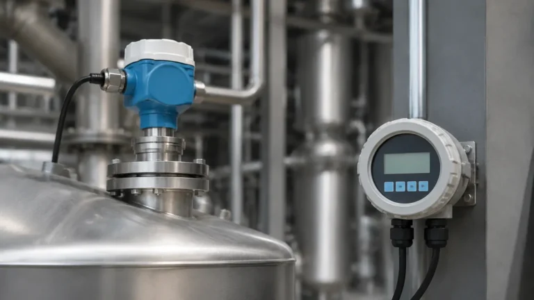
In the landscape of industrial automation, accurate level measurement is a critical prerequisite for process safety, inventory management, and operational efficiency. Among the various technologies available, radar-based systems have emerged as the gold standard for challenging environments. This guide explores the fundamentals of "radar level 1"—the essential baseline of knowledge required to select, install, and maintain radar level measurement systems in industrial settings.
Understanding Radar Level Measurement Principles
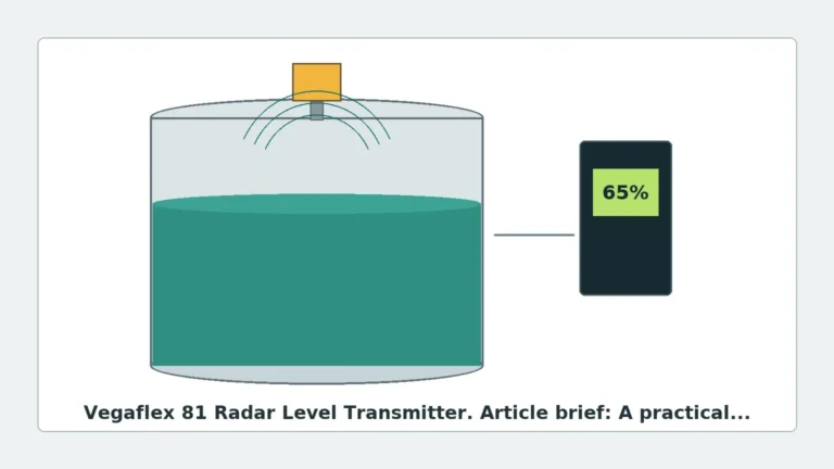
Before selecting a device, it is essential to understand the physics governing radar technology. Industrial radar level sensors utilize electromagnetic waves, typically in the microwave frequency range, to determine the distance from the sensor to the surface of a material. Unlike ultrasonic sensors, which rely on sound waves and are affected by air temperature and pressure, radar waves travel at the speed of light and are largely independent of the vapor space composition.
Time-of-Flight (ToF) vs. FMCW
There are two primary methods used by Radar Level Meters to calculate distance:
1. Pulse Radar (Time-of-Flight): The instrument emits a short microwave pulse toward the product surface. The pulse is reflected and received by the antenna. The distance is calculated based on the time it takes for the pulse to travel to the surface and back ($D = c \times t / 2$, where $c$ is the speed of light). This method is energy-efficient and suitable for many standard liquid applications.
2. Frequency Modulated Continuous Wave (FMCW): The sensor emits a continuous signal with a constantly changing frequency. The difference between the frequency of the emitted signal and the reflected signal is proportional to the distance. FMCW radar generally offers higher accuracy and a better signal-to-noise ratio, making it the preferred choice for low-dielectric materials or turbulent surfaces.
Contact vs. Non-Contact Radar
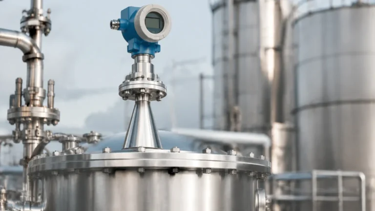
* Non-Contact Radar: The antenna is mounted at the top of the vessel and does not touch the medium. This is ideal for corrosive, hygienic, or extremely hot materials where sensor degradation is a concern.
* Guided Wave Radar (GWR): A probe (cable or rod) guides the microwave pulse directly to the surface. This is highly effective for low-dielectric liquids, foaming surfaces, or applications with internal tank obstructions that might interfere with a free-space beam.
Selection Criteria for Radar Level 1 Applications
Selecting the correct radar instrument requires a detailed analysis of the process environment. Engineers must consider several technical factors to ensure the device performs reliably over its service life.
1. Frequency Selection
The frequency of the radar signal significantly impacts its performance. Industrial radar typically operates in three main bands:
* 6 GHz (C-Band): Lower frequency waves are less affected by foam, dust, or heavy vapor. They have a wider beam angle, which makes them less suitable for narrow tanks with internal obstructions.
* 26 GHz (K-Band): A versatile middle ground. It offers a narrower beam than C-band and is suitable for a wide range of liquids and some solids.
* 80 GHz (W-Band): The modern standard for high precision. With a very narrow beam angle (often as low as 3 degrees), 80 GHz radar can avoid internal obstacles like agitators and ladders. It is also excellent for measuring through small nozzles.
2. Dielectric Constant (Dk)
The dielectric constant of the medium determines how much of the radar signal is reflected. Materials with high Dk (e.g., water, Dk ≈ 80) reflect signals strongly. Materials with low Dk (e.g., hydrocarbons or dry powders, Dk < 2) reflect very little energy, requiring more sensitive FMCW electronics or Guided Wave Radar to ensure a stable signal.
3. Process Conditions
* Temperature: Standard units often handle up to 150°C (302°F), but specialized high-temperature versions can exceed 450°C (842°F).
* Pressure: Applications range from vacuum conditions to high-pressure reactors exceeding 100 bar (1450 psi).
* Chemical Compatibility: The wetted parts (antenna or probe) must be compatible with the medium. Common materials include 316L stainless steel, PTFE, and Hastelloy.
Practical Selection Table
| Feature | Pulse Radar (Non-Contact) | FMCW Radar (Non-Contact) | Guided Wave Radar (GWR) |
| :— | :— | :— | :— |
| Best For | Clean liquids, large tanks | Low Dk liquids, solids, high precision | Foam, interface, narrow bypass pipes |
| Accuracy | ±2 mm to ±5 mm | ±1 mm to ±2 mm | ±2 mm |
| Beam Focus | Moderate | High (at 80 GHz) | N/A (signal follows probe) |
| Foam Handling | Poor to Moderate | Moderate | Good |
| Max Range | Up to 35 m | Up to 120 m | Up to 75 m |
Installation Considerations and Constraints
Even the most advanced radar level 1 system will fail if installed incorrectly. Engineering teams must adhere to strict mounting guidelines to prevent signal interference.
Nozzle Design
The mounting nozzle should be as short as possible. If the nozzle is too long or narrow, the radar signal may reflect off the nozzle's inner edge, creating a "ringing" effect that masks the true level of the product. For 80 GHz units, nozzle interference is minimized, but for lower frequencies, the nozzle height should ideally not exceed its diameter.
The 1/6th Rule
For non-contact radar, the sensor should generally be mounted at a distance from the tank wall equal to approximately 1/6th of the tank diameter. Mounting too close to the wall can cause parasitic reflections (multipath interference), while mounting in the exact center of a domed-roof tank can cause the roof to act as a parabolic reflector, concentrating noise at the sensor.
Obstructions and False Echo Suppression
Internal structures such as heating coils, ladders, and agitators create "false echoes." Modern radar software allows for "False Echo Mapping," where the sensor is taught to ignore static reflections from these objects. However, it is always better to position the sensor where the beam has a clear path to the product surface.
Limitations and Application Risks
While radar is highly versatile, it is not a universal solution. Engineers should be aware of the following limitations:
1. Heavy Foam: Extremely dense, thick foam can absorb the radar signal entirely, leading to a "loss of echo" error. In these cases, Guided Wave Radar or differential pressure transmitters may be more appropriate.
2. Rapid Turbulence: While radar can handle some surface movement, extreme turbulence can scatter the signal. Software damping and FMCW technology help mitigate this.
3. Condensation and Buildup: In high-humidity applications, water droplets can form on the antenna. While many antennas are designed to be self-draining, heavy buildup of viscous or crystallizing products can attenuate the signal.
Maintenance and Troubleshooting
Radar sensors are solid-state devices with no moving parts, which naturally reduces maintenance requirements. However, a routine check should include:
* Visual Inspection: Check the antenna or probe for material buildup or corrosion.
* Signal Quality Analysis: Most modern digital transmitters (HART, Profibus, Foundation Fieldbus) provide a signal-to-noise ratio or echo curve. A declining signal strength over time may indicate antenna fouling or a change in the process medium's dielectric properties.
* Verification: Periodically verify the radar reading against a manual dip-tape or a secondary level gauge to ensure calibration has not drifted.
Frequently Asked Questions (FAQ)
Q: Can radar measure the interface between two liquids?
A: Yes, Guided Wave Radar is particularly effective at measuring the interface between a low-Dk upper layer (like oil) and a high-Dk lower layer (like water). The signal reflects off both the top surface and the interface layer.
Q: Is radar safe for use in explosive atmospheres?
A: Yes, most industrial radar level meters are available with ATEX, IECEx, or FM certifications for use in Zone 0, 1, or 2 hazardous areas, utilizing Intrinsically Safe (Ex i) or Explosion-Proof (Ex d) protection methods.
Q: Does the color or transparency of the liquid affect the measurement?
A: No. Unlike optical or laser sensors, radar is unaffected by the color, transparency, or opacity of the medium. It is solely dependent on the dielectric constant.
Conclusion for International Buyers
When sourcing radar level 1 equipment, international procurement teams should provide the manufacturer with a complete data sheet. This should include the vessel height, nozzle dimensions, chemical composition of the medium, dielectric constant, operating temperature/pressure range, and any required hazardous area certifications. By understanding these fundamental principles and selection criteria, engineers can ensure they implement a robust level measurement solution that minimizes downtime and maximizes process reliability.