Rosemount Radar Level Transmitter 5300 Calibration
Rosemount Radar Level Transmitter 5300 Calibration: An Engineering Guide
In the landscape of industrial automation, precision in liquid and solid level measurement is paramount for process safety, inventory management, and operational efficiency. The Rosemount 5300 series, a high-performance Guided Wave Radar (GWR) transmitter, is widely utilized in challenging environments ranging from oil and gas separators to chemical storage tanks. However, the reliability of these instruments depends heavily on correct commissioning and periodic verification. This guide provides a technical overview of the rosemount radar level transmitter 5300 calibration process, the underlying physics of Guided Wave Radar, and the critical factors an engineer must consider when selecting and maintaining Radar Level Meters.
Understanding Guided Wave Radar (GWR) Principles
Before initiating the calibration of a Rosemount 5300, it is essential to understand the measurement principle it employs: Time Domain Reflectometry (TDR). Unlike non-contact radar, which propagates electromagnetic waves through the air, GWR technology guides low-power microwave pulses along a physical probe submerged in the process medium.
The TDR Measurement Cycle
1. Pulse Emission: The transmitter electronics generate a microwave pulse that travels down the probe at the speed of light.
2. Reflection: When the pulse encounters a change in the dielectric constant ($ε_r$)—typically the transition from vapor space to the liquid or solid surface—a portion of the energy is reflected back to the transmitter.
3. Time-of-Flight Calculation: The transmitter measures the time elapsed between the emission and the reception of the reflected pulse. Since the speed of light is constant, the distance to the surface is calculated as:
*Distance = (Speed of Light × Time-of-Flight) / 2*
4. Level Conversion: The instrument subtracts the measured distance from the total tank height (configured during setup) to determine the product level.
Guided Wave Radar is particularly effective in applications with low dielectric constants, high turbulence, or foaming, where non-contact radar might struggle to receive a clear return signal.
Rosemount Radar Level Transmitter 5300 Calibration Procedures
Calibration of the Rosemount 5300 is generally performed using software tools like Emerson’s Radar Master, a Field Communicator (HART), or via a control system interface. The process involves defining the physical boundaries of the vessel and the electrical properties of the medium.
1. Bench Calibration vs. Field Configuration
While "calibration" in a laboratory sense involves verifying accuracy against a known standard, in the context of GWR, it usually refers to "configuration." Because the probe length is fixed, the transmitter must be told exactly where the 0% (4mA) and 100% (20mA) points reside relative to the probe's reference point.
2. Key Parameters for Configuration
To ensure accurate readings, the following parameters must be entered into the device:
* Probe Length: The exact distance from the flange face to the end of the probe. Any discrepancy here will result in a zero-shift error.
* Dielectric Constant (ε_r): This is the most critical variable. If the dielectric constant of the medium is unknown, the transmitter may fail to distinguish the surface from background noise. For water-based liquids, ε_r is high (~80); for hydrocarbons, it is low (1.9 to 2.5).
* Upper Range Value (URV): The level corresponding to the 20mA output (typically the maximum fill level).
* Lower Range Value (LRV): The level corresponding to the 4mA output (typically the tank bottom or the end of the probe).
3. Handling the Upper Null Zone
The Rosemount 5300 has an "Upper Null Zone" (or transition zone) near the flange where measurements may be less accurate due to signal ringing. During calibration, engineers must ensure the URV is set below this zone to avoid erratic readings when the tank is nearly full. This zone typically ranges from 100mm to 500mm depending on the probe type and dielectric constant.
Selection Criteria for Radar Level Instrumentation
Choosing the right probe and transmitter configuration is a prerequisite for successful calibration. The following table summarizes the selection criteria for various industrial scenarios.
| Application Feature | Probe Recommendation | Calibration Consideration |
| :— | :— | :— |
| Clean Liquids (High ε_r) | Single Lead Probe | Simple calibration; high signal strength. |
| Low Dielectric (Oil/Fuel) | Coaxial or Twin Lead | Requires precise ε_r setting to amplify weak reflections. |
| Viscous/Coating Fluids | Single Lead (Thick) | Must account for signal attenuation due to buildup. |
| Interface (Oil over Water) | Large Diameter Coaxial | Requires configuration of both upper and lower dielectric constants. |
| Solids/Powders | Flexible Cable Probe | Must account for pull-down forces and angle of repose. |
Installation Constraints and Best Practices
Even a perfectly calibrated rosemount radar level transmitter 5300 will provide inaccurate data if the physical installation is flawed. Engineers must adhere to the following constraints:
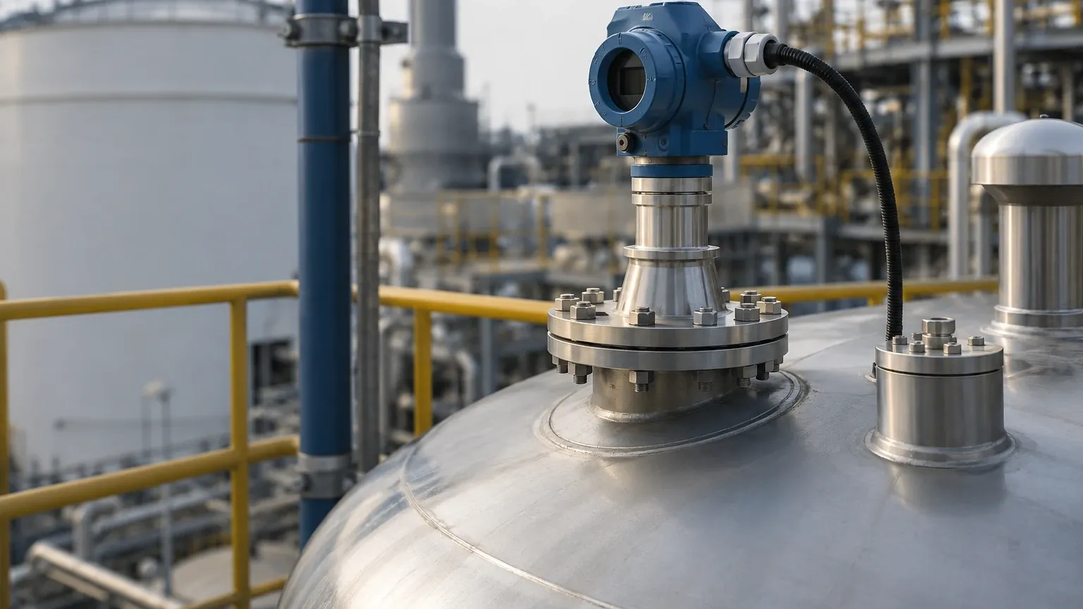
1. Nozzle Interference: The nozzle diameter and height must allow the pulse to transition onto the probe without reflecting off the nozzle walls. For single-lead probes, a nozzle diameter of at least 50mm (2 inches) is recommended.
2. Internal Obstructions: The probe should be installed at least 300mm (12 inches) away from agitators, ladders, or inflow pipes to prevent parasitic reflections (ghost echoes).
3. Probe Centering: In bypass chambers or stilling wells, the probe must be centered. Contact with the metal wall will short the signal, leading to a "Low Signal" or "High Level" error.
4. Metric Standardization: For international projects, ensure all measurements are recorded in millimeters (mm) or meters (m) to align with standard engineering documentation, although imperial units (inches/feet) are supported by the transmitter firmware.
Application Risks and Limitations
While GWR is robust, it is not universal. Understanding its limitations is vital for B2B buyers and plant engineers:
* Dielectric Limits: If the medium has a dielectric constant lower than 1.4, the reflection may be too weak for the Rosemount 5300 to detect reliably without a coaxial probe.
* Probe Coating: While the 5300 series features advanced Signal Quality Metrics (SQM) to compensate for buildup, extreme coating (e.g., dehydrated bitumen) can cause signal loss.
* Vapor Phase Compensation: In high-pressure steam applications (e.g., boiler drums), the speed of the radar pulse slows down in the dense vapor. Without a Dynamic Vapor Compensation (DVC) probe, the transmitter will report a level lower than the actual value.
Information for International Procurement
When sourcing Radar Level Meters for global operations, procurement teams should confirm the following with the manufacturer or supplier:
1. Process Connection Standards: Ensure flanges meet ANSI, DIN, or JIS standards as required by the site piping specification.
2. Hazardous Area Certifications: Verify ATEX, IECEx, or FM approvals for explosive atmospheres.
3. Probe Material Compatibility: Confirm that the wetted parts (316L Stainless Steel, Hastelloy, PTFE) are compatible with the process chemical composition.
4. Communication Protocol: Specify HART 7, Foundation Fieldbus, or Modbus RS485 to ensure compatibility with the existing DCS/PLC architecture.
Frequently Asked Questions (FAQ)
Q: How often should a Rosemount 5300 be recalibrated?
A: In stable processes, GWR transmitters do not "drift" like pressure transmitters. Verification is typically recommended every 12 to 24 months, or during major plant turnarounds, primarily to check for probe integrity and buildup.
Q: Can I calibrate the transmitter with an empty tank?
A: Yes. One of the advantages of GWR is that it can be fully configured using the probe length and dielectric constant without needing to fill the tank to specific levels.
Q: What causes a "Probe End Found" error during calibration?
A: This usually occurs if the transmitter is searching for a surface reflection but only sees the reflection from the end of the probe. This happens if the tank is empty or if the dielectric constant of the liquid is so low that the signal passes through it.
Q: How does foam affect the 5300 calibration?
A: GWR is generally foam-resistant. However, if the foam is very dense and metallic, it may reflect the signal prematurely. In such cases, adjusting the threshold sensitivity in the software is necessary.
Conclusion
The rosemount radar level transmitter 5300 calibration is a technical process that bridges the gap between electromagnetic theory and practical industrial application. By accurately defining the probe length, dielectric properties, and vessel geometry, engineers can leverage the full precision of GWR technology. For those seeking versatile and cost-effective alternatives for diverse industrial automation needs, exploring a wide range of Radar Level Meters ensures that the selected technology aligns with the specific chemical, thermal, and mechanical demands of the process environment.
Download Rosemount Radar Level Transmitter 5300 Calibration as a PDF