Ultrasonic G
Ultrasonic G
In the landscape of industrial automation, the term "Ultrasonic G" often refers to the broad category of general-purpose ultrasonic level gauges used for non-contact distance and level monitoring. For process engineers and facility managers, selecting the right instrumentation is a balance between precision, environmental compatibility, and cost-effectiveness. Ultrasonic level meters have become a staple in industries ranging from water treatment to chemical processing due to their lack of moving parts and ease of installation.
This guide provides a technical overview of the measurement principles, selection criteria, and practical installation requirements for Ultrasonic Level Meters, ensuring that your project specifications align with the physical realities of your process environment.
Understanding the Principles of Ultrasonic Level Meters
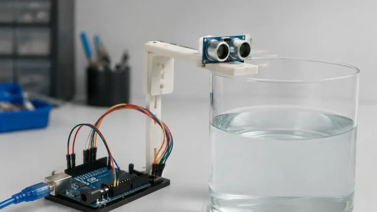
Before selecting an Ultrasonic G series gauge, it is essential to understand the underlying physics that govern its operation. Ultrasonic measurement is based on the "Time-of-Flight" (ToF) principle.
The Time-of-Flight Principle
The sensor, typically a piezoelectric transducer, emits a high-frequency acoustic pulse (usually between 20 kHz and 200 kHz). This pulse travels through the air or gas space above the medium, strikes the surface of the material (liquid or solid), and reflects back to the sensor. The instrument measures the time interval ($t$) between the emission of the pulse and the reception of the echo.
The distance ($D$) from the sensor to the material surface is calculated using the formula:
$$D = \frac{c \times t}{2}$$
Where:
* $c$ is the speed of sound in the medium (typically air).
* $t$ is the total travel time of the pulse.
The level of the material is then derived by subtracting the measured distance from the total height of the tank or vessel.
The Role of Temperature Compensation
The speed of sound ($c$) is not a constant; it varies significantly with temperature. In air, the speed of sound changes by approximately 0.17% per degree Celsius. To maintain accuracy, most industrial Ultrasonic G units include an integrated temperature sensor. This allows the internal microprocessor to adjust the calculation in real-time, compensating for fluctuations in the ambient air temperature within the tank headspace.
Defining the Ultrasonic G: General Purpose vs. Specialized Gauging
In professional engineering contexts, "Ultrasonic G" typically denotes instruments designed for standard atmospheric or low-pressure applications. These units are categorized by their physical architecture and electrical configuration:
1. Integrated (Compact) Design: The transducer and the signal processing electronics are housed in a single unit. These are ideal for space-constrained environments and simplified wiring.
2. Split (Remote) Design: The transducer is mounted on the vessel, while the display and control unit are located in a remote cabinet or control room. This is preferred for high-temperature applications or where the sensor is located in a hazardous or inaccessible area.
3. 2-Wire vs. 4-Wire Systems:
* 2-Wire (Loop-Powered): The device is powered by the 4-20mA signal loop. These are energy-efficient and reduce cabling costs.
* 4-Wire: Separate power supply and signal lines. These units typically offer higher acoustic power, making them better suited for challenging environments with dust or long distances.
Key Selection Criteria for Industrial Applications
Choosing an Ultrasonic G gauge requires a thorough analysis of the process medium and the vessel geometry. Use the following table as a preliminary reference for selection.
Practical Selection Table
| Feature | Standard Liquid Application | Solids/Powder Application | Corrosive Environments |
| :— | :— | :— | :— |
| Measuring Range | 0.3m to 15m | 0.5m to 10m (reduced range) | 0.3m to 10m |
| Transducer Material | ABS / PVC | Reinforced Polymer | PVDF / PTFE |
| Beam Angle | 6° to 12° | 5° to 8° (narrower is better) | 8° to 12° |
| Output Signal | 4-20mA / HART | 4-20mA / Modbus | 4-20mA / HART |
| Accuracy | ±0.2% to 0.5% of range | ±1% of range | ±0.5% of range |
| Pressure Limit | ≤ 0.3 MPa | ≤ 0.1 MPa | ≤ 0.2 MPa |
Material Compatibility
For standard water treatment, ABS or PVC housings are sufficient. However, in the chemical industry, the transducer face is the most vulnerable component. If the medium emits corrosive vapors (such as hydrochloric acid or ammonia), a PVDF or PTFE-faced transducer is mandatory to prevent degradation of the piezoelectric element.
Installation Guidelines for Accurate Measurement
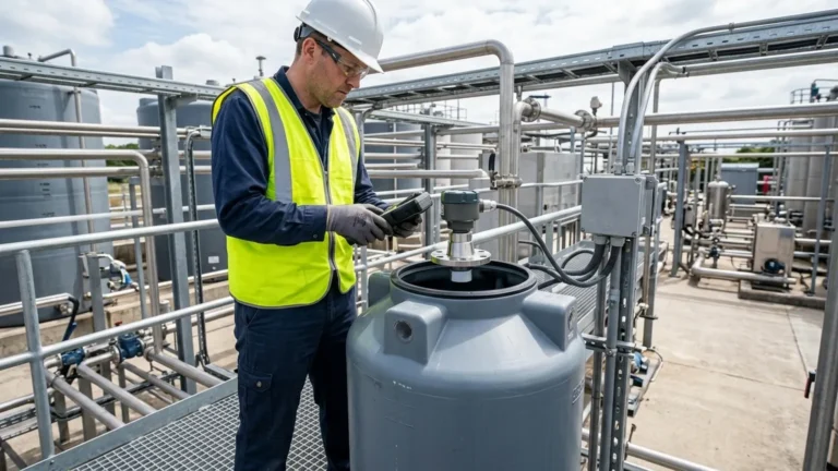
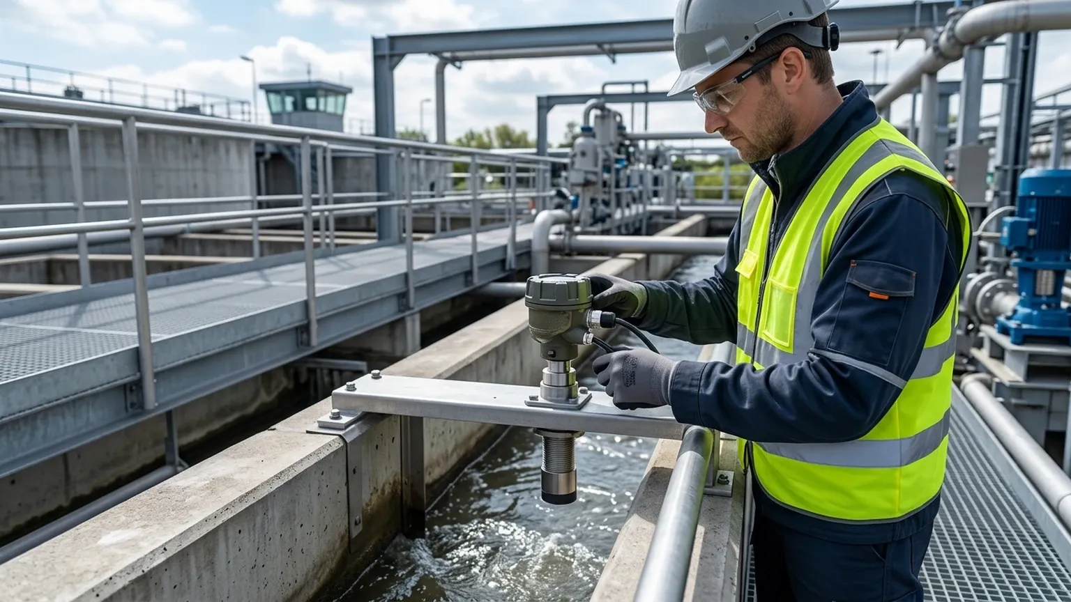
The most common cause of failure in ultrasonic level systems is improper installation. To ensure the Ultrasonic G gauge provides a reliable signal, several geometric and physical factors must be considered.
1. The Dead Zone (Blanking Distance)
Every ultrasonic sensor has a "dead zone" immediately below the transducer face where it cannot measure. This is the time required for the transducer to stop vibrating after emitting a pulse so it can act as a receiver. If the liquid level enters this zone, the reading will become erratic or lock at the maximum value. Always mount the sensor high enough so that the maximum liquid level never reaches the dead zone (typically 0.2m to 0.5m depending on the model).
2. Mounting Position and the 1/6th Rule
To avoid false echoes from the tank walls, the sensor should not be mounted too close to the side of the vessel. A general rule of thumb is to install the sensor at a distance of 1/6th of the tank diameter from the wall.
* Avoid the Center: Do not mount the sensor in the exact center of a dome-roofed tank, as this can create a parabolic effect that amplifies unwanted noise.
* Avoid Inlets: Never mount the sensor directly above the fill stream. The falling liquid or solids will intercept the ultrasonic pulse and cause false readings.
3. Beam Angle and Obstructions
The ultrasonic pulse spreads out in a cone shape. Any internal obstructions within this cone—such as ladders, heating coils, or agitators—will reflect the signal. If an obstruction is unavoidable, many modern Ultrasonic G gauges offer "false echo suppression" software, allowing the user to map out and ignore static reflections.
4. Standpipe Considerations
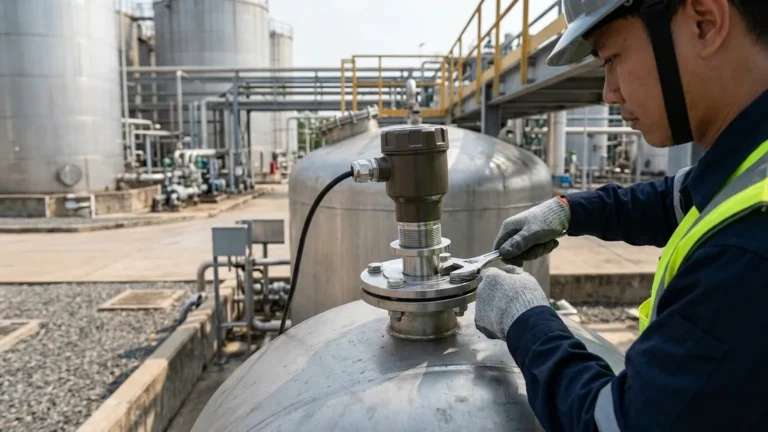
If the sensor must be mounted on a nozzle or standpipe, the pipe must be smooth and free of burrs. If the standpipe is too narrow or too long, the pulse will reflect off the pipe walls before reaching the medium. The diameter of the nozzle should be wide enough to accommodate the beam angle of the sensor at the nozzle's exit point.
Limitations and Environmental Challenges
While Ultrasonic G instruments are versatile, they are not universal solutions. Understanding their limitations is critical for process safety.
* Foam: Heavy, thick foam on the surface of a liquid acts as an acoustic absorber. It can soak up the ultrasonic pulse, resulting in a "Lost Echo" error. For foaming liquids, radar level meters or hydrostatic transmitters are often better alternatives.
* Vacuum and Pressure: Sound requires a medium to travel. In a vacuum, ultrasonic sensors cannot function. Similarly, high-pressure environments change the density of the air, significantly altering the speed of sound and complicating the measurement.
* Dust and Steam: While light dust is manageable, heavy dust in grain silos or dense steam in boiling tanks can scatter the acoustic signal. In these cases, high-frequency radar is typically recommended.
* Turbulence: Extreme surface turbulence can deflect the ultrasonic pulse away from the receiver. This can sometimes be mitigated by using a stilling well (a vertical pipe that stabilizes the liquid surface).
Maintenance and Troubleshooting
Ultrasonic G gauges are low-maintenance because they do not touch the process media. However, periodic checks are recommended:
1. Transducer Cleaning: In high-humidity or splashing environments, condensation or residue can build up on the transducer face. Wipe it periodically with a soft cloth and mild solvent.
2. Cable Integrity: Ensure that cable glands are tight to prevent moisture ingress into the electronics housing.
3. Recalibration: While the electronics do not drift significantly, changes in the gas composition in the tank headspace (e.g., a shift from air to Nitrogen) will change the speed of sound and require a recalibration of the distance constant.
Frequently Asked Questions (FAQ)
Q: Can Ultrasonic G sensors be used for solids?
A: Yes, but with caveats. Solids like grain or plastic pellets do not reflect sound as efficiently as liquids. They also tend to form conical piles rather than flat surfaces. For solids, choose a sensor with a higher power output and a narrower beam angle.
Q: What is the maximum temperature an ultrasonic sensor can handle?
A: Most integrated sensors are rated up to 60°C or 80°C. For higher temperatures, a split-type system is used to keep the electronics away from the heat, but the transducer itself is still limited by the physical properties of the piezoelectric material and the housing.
Q: How do I handle a "Lost Echo" alarm?
A: First, check if the level is in the dead zone. Second, inspect the transducer face for dirt or condensation. Third, verify that there isn't excessive foam or turbulence. If the application has changed (e.g., a different chemical is being used), the speed of sound compensation may need adjustment.
For engineers seeking to integrate these solutions into their control systems, reviewing specific Ultrasonic Level Meters technical data sheets is the final step in ensuring hardware compatibility with local PLC or SCADA requirements. By adhering to the physical constraints of acoustic measurement and following disciplined installation practices, the Ultrasonic G category remains one of the most reliable methods for modern level monitoring.