Ultrasonic Level Sensor Kit
Understanding the Ultrasonic Level Sensor Kit: A Practical Engineering Guide
In the landscape of industrial automation, non-contact level measurement has become a standard for managing liquids and solids across diverse sectors. Among the various technologies available, the ultrasonic level sensor kit represents a versatile and cost-effective solution for many standard applications. This guide examines the technical principles, selection criteria, and installation requirements for implementing ultrasonic measurement systems in industrial environments.
Measurement Principles of Ultrasonic Technology
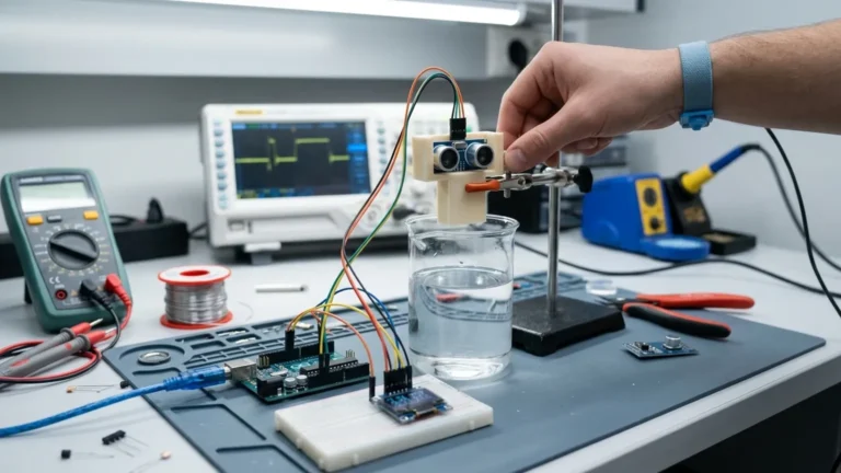
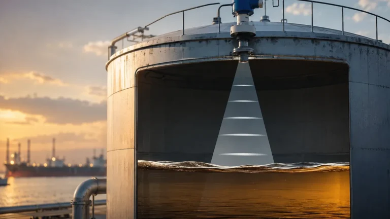
Ultrasonic level measurement is based on the "Time-of-Flight" (ToF) principle. The sensor, typically a piezoelectric transducer, emits high-frequency sound pulses—usually in the range of 20 kHz to 200 kHz. These sound waves travel through the air, reflect off the surface of the medium (liquid or solid), and return to the transducer.
The Calculation Process
The internal electronics of the Ultrasonic Level Meters calculate the distance between the sensor face and the material surface using the following formula:
Distance = (Speed of Sound × Time Delay) / 2
Since the speed of sound in air is approximately 344 m/s at 20°C, the system must account for environmental variables. The most critical variable is temperature, as the speed of sound changes by approximately 0.17% per degree Celsius. Most professional-grade kits include an integrated temperature sensor to provide real-time compensation, ensuring accuracy remains within the typical range of 0.25% to 0.5% of the measured span.
Components of an Ultrasonic Level Sensor Kit
A complete ultrasonic level sensor kit is designed to provide all necessary components for immediate deployment. While configurations vary based on the application, a standard industrial kit typically includes:
1. The Transducer/Transmitter: The core component that houses the piezoelectric crystal and the processing electronics. In "compact" designs, the display and output modules are integrated into this single unit.
2. Controller/Display Unit: In "split" or remote configurations, the transducer is separated from the controller. This allows the display to be mounted at eye level or in a control room while the sensor is at the top of a tall tank.
3. Mounting Hardware: This often includes threaded nuts, flanges, or adjustable brackets designed to secure the sensor at the correct orientation.
4. Cabling: For remote kits, specialized shielded cables are provided to minimize electromagnetic interference (EMI) between the sensor and the controller.
5. Configuration Software/Interface: Modern kits may include a digital interface (such as HART, Modbus, or a proprietary USB adapter) for fine-tuning the signal processing parameters via a PC.
Key Evaluation Criteria for Selection
Choosing the right ultrasonic level sensor kit requires a detailed understanding of the process environment. Engineers must evaluate the following factors to ensure long-term reliability.
Measurement Range and Dead Zone
Every ultrasonic sensor has a "dead zone" (also known as the blocking distance). This is a small area directly in front of the transducer face where the sensor cannot accurately process the returning signal because it is still vibrating from the transmission. Typical dead zones range from 0.2 meters to 0.5 meters. If the material level rises into this zone, the sensor will provide an error or an incorrect reading.
Material Characteristics
Ultrasonic waves reflect best off hard, flat surfaces. Liquids are generally excellent reflectors. However, granulated solids (like grain or plastic pellets) may scatter the sound waves, requiring a sensor with a higher power output or a more sensitive receiver. If the liquid surface is prone to heavy foam, the foam may absorb the ultrasonic pulse entirely, leading to a loss of signal.
Environmental Conditions
* Pressure: Ultrasonic sensors are generally limited to near-atmospheric pressure. Significant pressure changes alter the density of the air, which in turn affects the speed of sound beyond what standard temperature compensation can handle.
* Chemical Compatibility: The transducer face (often made of PVDF, PP, or PTFE) must be compatible with the vapors present in the tank.
Practical Selection Table
| Application Type | Recommended Range | Typical Output | Housing Material |
| :— | :— | :— | :— |
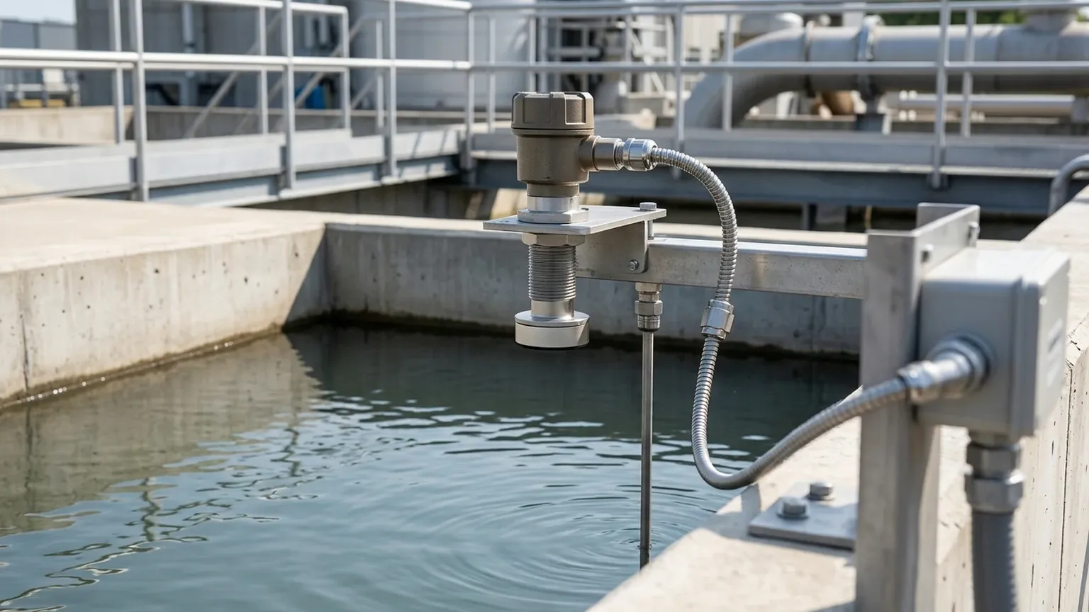
| Open Water Channels | 0 – 5 meters | 4-20mA / Modbus | Polypropylene (PP) |
| Chemical Storage Tanks | 0 – 10 meters | 4-20mA + HART | PVDF |
| Tall Silos (Solids) | 0 – 15+ meters | 4-20mA / Relay | Reinforced Plastic/AL |
| Small Process Vats | 0 – 2 meters | 0-10V / PNP/NPN | Stainless Steel/Plastic |
Installation Considerations and Best Practices
Proper physical installation is the most influential factor in the performance of an ultrasonic level sensor kit. Even the most advanced electronics cannot compensate for a poorly positioned transducer.
1. Perpendicular Alignment
The transducer must be mounted so that the sensor face is perfectly parallel to the liquid surface. If the sensor is tilted, the ultrasonic pulse will reflect off the surface at an angle and may not return to the receiver, resulting in an "Echo Loss" error.
2. Beam Angle and Obstructions
Ultrasonic pulses propagate in a cone shape, typically between 5° and 12°. It is vital to ensure that no internal tank structures—such as ladders, pipes, or agitators—intersect this beam path. If an obstruction is unavoidable, many Welk systems offer "False Echo Suppression," allowing the software to ignore fixed reflections from internal structures.
3. Avoiding Turbulence and Fill Streams
Sensors should never be mounted directly above the point where the tank is filled. The falling liquid creates turbulence and air bubbles that scatter the signal. Ideally, the sensor should be placed at a distance of at least 20% of the tank radius away from the wall to avoid interference from wall seams or scale buildup.
Limitations of Ultrasonic Technology
While highly effective for many applications, ultrasonic level sensor kits have specific physical boundaries:
* Vacuum Applications: Sound waves require a medium (air or gas) to travel. Therefore, ultrasonic sensors cannot function in a vacuum.
* High Dust Environments: While some dust is manageable, extremely dense dust clouds (common during the pneumatic filling of silos) can attenuate the signal.
* Extreme Temperatures: Most ultrasonic sensors are rated up to 70°C or 80°C. For high-temperature steam or furnace applications, radar technology is typically preferred.
* Vapor Layers: Heavy concentrations of chemical vapors (like those from solvents) can change the gas composition in the tank, leading to measurement errors because the speed of sound in those vapors differs from the speed of sound in air.
Frequently Asked Questions (FAQ)
Q: Can I use an ultrasonic sensor to measure the level of a powder?
A: Yes, but with caveats. You must select a sensor specifically designed for solids, which usually features a lower frequency to penetrate dust and a narrower beam angle. The "angle of repose" of the powder must also be considered, as the slope can reflect the signal away from the sensor.
Q: How do I handle heavy foam on the liquid surface?
A: Light foam may be penetrable, but thick, dense foam usually absorbs the ultrasonic signal. In these cases, a stilling well (a vertical pipe that breaks the foam) can be used, or you may need to switch to a different technology like a hydrostatic pressure transmitter or a guided wave radar.
Q: What is the maximum distance an ultrasonic sensor can measure?
A: Most industrial ultrasonic level meters are effective up to 15 or 20 meters. Beyond this range, the signal attenuation in the air becomes significant, and radar is generally a more reliable choice.
Q: Does the color of the liquid affect the measurement?
A: No. Unlike optical or laser sensors, ultrasonic technology is completely unaffected by the color, transparency, or opacity of the medium.
Conclusion for Project Planning
An ultrasonic level sensor kit provides a reliable, non-contact means of monitoring levels in water treatment, chemical storage, and industrial automation. By understanding the relationship between the speed of sound and environmental variables, and by adhering to strict installation guidelines regarding beam angles and dead zones, engineers can implement a low-maintenance solution that offers years of accurate service. For applications involving extreme pressures, vacuums, or heavy foam, consulting with a technical specialist to compare ultrasonic performance against radar or hydrostatic alternatives is recommended to ensure the highest level of process safety and efficiency.