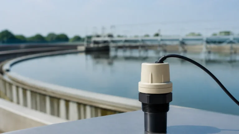
Ultrasonic Level Sensor with Remote Display
Ultrasonic Level Sensor with Remote Display: A Comprehensive Engineering Guide
In modern industrial process control, the ability to monitor liquid and solid levels accurately without physical contact is a significant operational advantage. Among the various technologies available, Ultrasonic Level Meters have emerged as a primary choice for engineers due to their reliability, cost-effectiveness, and ease of maintenance. A specific configuration that has gained traction in complex plant layouts is the ultrasonic level sensor with remote display, which separates the sensing element from the monitoring interface to enhance safety and accessibility.
This guide explores the fundamental principles of ultrasonic measurement, the technical advantages of remote display configurations, and the critical factors for selection and installation in industrial environments.
1. Understanding the Measurement Principle
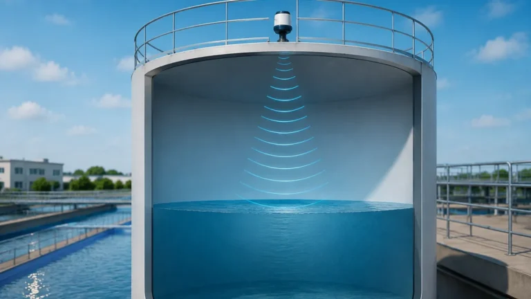
Ultrasonic level measurement is based on the "Time-of-Flight" (ToF) principle. The sensor, typically mounted at the top of a vessel, contains a piezoelectric transducer that emits high-frequency acoustic pulses. These sound waves travel through the air space inside the tank, strike the surface of the medium, and reflect back to the sensor.
The Calculation Logic
The device calculates the distance ($D$) between the sensor and the material surface using the formula:
$$D = \frac{c \times t}{2}$$
Where:
* $c$ is the speed of sound in the medium (usually air).
* $t$ is the total time elapsed between the emission of the pulse and the reception of the echo.
Since the height of the tank ($H$) is a known constant entered during calibration, the actual level ($L$) is determined by subtracting the measured distance from the total height ($L = H – D$).
Temperature Compensation
The speed of sound is not constant; it fluctuates based on the ambient temperature. For instance, sound travels faster in warmer air. To maintain high accuracy, professional-grade Ultrasonic Level Meters incorporate an internal temperature sensor to automatically compensate for these variations, ensuring the measurement remains precise across shifting environmental conditions.
2. Why Choose an Ultrasonic Level Sensor with Remote Display?
While integrated (all-in-one) sensors are common, the ultrasonic level sensor with remote display (often referred to as a split-type meter) offers distinct advantages in specific industrial scenarios.
Enhanced Accessibility and Safety
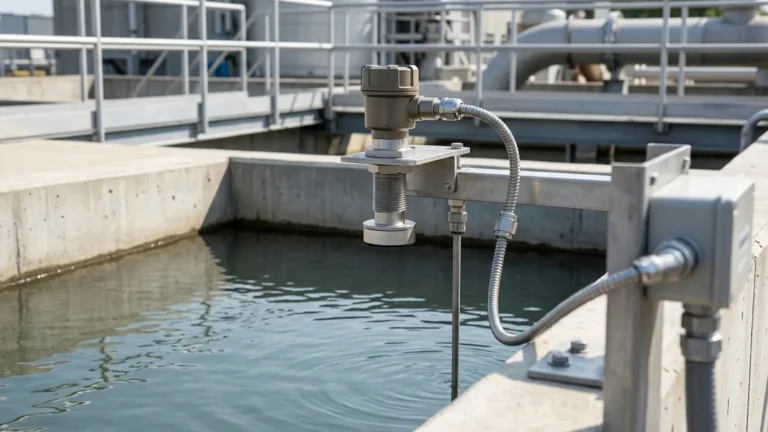
In many chemical or water treatment facilities, sensors are installed on top of tall silos or in hazardous areas. Reading a local display in these locations requires personnel to climb ladders or wear specialized protective gear. By using a remote display, the transmitter (the host) can be installed at eye level or within a control room, allowing operators to monitor levels safely and conveniently.
Signal Stability and Integration
Remote display units often serve as more than just a visual interface. They frequently act as the central hub for power management and signal processing. These units can convert the raw data from the probe into various industrial outputs, such as 4-20mA analog signals, RS485 (Modbus), or relay outputs for pump control and high/low-level alarms.
Protection of Electronics
In applications involving high vibration or extreme temperatures at the measurement point, the split-type design allows the sensitive electronic components in the display unit to be housed in a more stable environment, extending the overall lifespan of the instrument.
3. Key Selection Criteria
Selecting the right instrument requires a thorough understanding of the application's physical and chemical constraints. Use the following table as a preliminary reference for evaluating configurations:
| Feature | Integrated Ultrasonic Meter | Ultrasonic Level Sensor with Remote Display |
| :— | :— | :— |
| Installation Effort | Low (Single point) | Moderate (Requires cabling between probe and host) |
| Display Visibility | Limited to the top of the tank | Highly accessible at eye level |
| Protection Class | Usually IP65/IP67 | Probe: IP68; Host: IP65 |
| Cable Length | N/A | Typically up to 50–100 meters |
| Application | Small tanks, simple monitoring | Large silos, sumps, hazardous zones |
| Cost | Budget-friendly | Premium (due to separate housing and cabling) |
Measuring Range and Dead Zone
Every ultrasonic sensor has a "Dead Zone" (or blocking distance), which is the area immediately below the transducer where measurements cannot be taken. This is caused by the time the transducer needs to stop vibrating after emitting a pulse before it can listen for the return echo. Common dead zones range from 0.2m to 0.5m (approx. 8" to 20"). It is vital to ensure the maximum expected level never enters this zone.
Media Characteristics
While ultrasonic technology is excellent for water and most chemicals, it can struggle with heavy foam or dust. Foam absorbs the acoustic pulse, while heavy dust in a silo can scatter the signal. In these instances, radar level meters may be a more appropriate alternative, though ultrasonic remains the cost-effective standard for most liquid applications.
4. Installation Guidelines and Best Practices
Proper installation is the most critical factor in ensuring the long-term accuracy of an ultrasonic level sensor with remote display. Even the most advanced sensor will fail if placed incorrectly.
Positioning the Probe
1. Avoid the Center: Do not mount the sensor in the exact center of a circular tank, as this can create a "parabolic" effect that amplifies unwanted echoes.
2. Stay Away from Inlets: Ensure the sensor is not positioned directly above the fill stream. The turbulence and falling material will interfere with the acoustic signal.
3. Beam Angle Awareness: The ultrasonic pulse spreads out in a cone (typically 5° to 12°). Ensure there are no internal obstructions, such as ladders, pipes, or agitators, within this beam path. If obstructions are unavoidable, many modern meters offer "False Echo Suppression" software to ignore these static reflections.
Mounting Requirements
The sensor must be mounted perpendicular to the liquid surface. If the sensor is tilted, the echo may reflect off the tank wall rather than returning to the transducer, resulting in a loss of signal. For solid materials that form a conical pile, an adjustable flange may be required to aim the sensor at the most representative point of the surface.
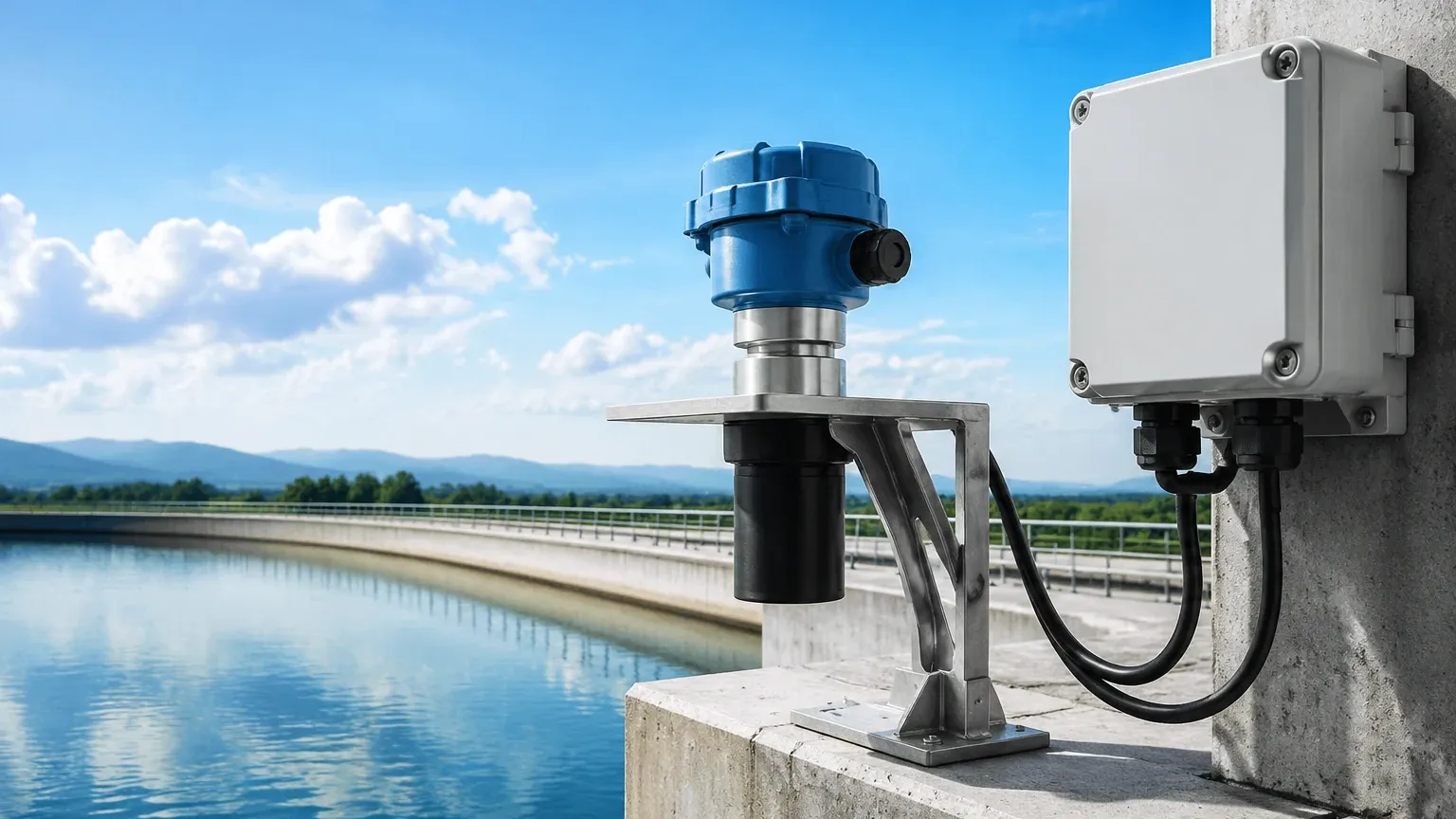
Wiring the Remote Display
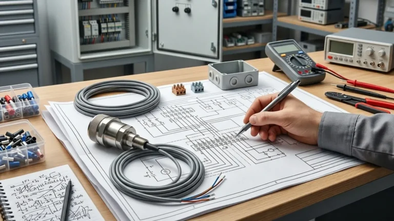
When installing a split-type system, use shielded twisted-pair cables to connect the probe to the remote display. This prevents electromagnetic interference (EMI) from nearby high-voltage equipment or variable frequency drives (VFDs) from corrupting the measurement signal.
5. Technical Limitations and Environmental Factors
Engineers must be aware of the physical boundaries of ultrasonic technology to avoid application failure:
* Vacuum Conditions: Ultrasonic waves require a medium (air or gas) to travel. They cannot function in a vacuum.
* Pressure Extremes: Most ultrasonic sensors are designed for atmospheric pressure. High-pressure environments can alter the speed of sound significantly and may damage the transducer face.
* Vapor and Steam: Heavy steam or high concentrations of volatile organic compounds (VOCs) can change the density of the air, affecting the speed of sound and potentially attenuating the signal.
* Surface Turbulence: Rapidly churning liquids can scatter the acoustic pulse. In these cases, a stilling well (a vertical pipe) can be used to provide a calm surface for the sensor to measure.
6. Maintenance and Troubleshooting
One of the primary benefits of Ultrasonic Level Meters is that they are virtually maintenance-free because they have no moving parts. However, occasional checks are recommended:
1. Transducer Face Cleaning: In humid or dusty environments, condensation or buildup may occur on the sensor face. A gentle wipe with a soft cloth is usually sufficient to restore performance.
2. Cable Integrity: For remote display models, inspect the cable connections periodically for signs of corrosion or wear, especially in outdoor installations.
3. Diagnostic Codes: Most digital remote displays will provide error codes (e.g., "Loss of Echo"). This is often solved by re-aligning the probe or adjusting the sensitivity settings in the host menu.
7. Frequently Asked Questions (FAQ)
Q: What is the maximum distance a remote display can be from the sensor?
A: Most industrial systems support a distance of 50 to 100 meters (approx. 164 to 328 feet) using standard shielded cabling. For longer distances, digital communication protocols like RS485 are preferred to maintain signal integrity.
Q: Can an ultrasonic level sensor with remote display be used for solids?
A: Yes, but with caveats. Solids like grain, plastic pellets, or coal tend to absorb sound more than liquids. You should select a sensor with a higher power output and a range rating at least double the actual height of the silo to account for signal attenuation.
Q: How does wind affect the measurement?
A: In outdoor open-channel flow or sump applications, strong winds can "blow" the acoustic pulse away from the receiver. In such cases, using a protective sunshade or a stilling tube can help stabilize the reading.
Q: Is it possible to use one remote display for multiple sensors?
A: Yes, multi-channel controllers are available that can interface with 2, 4, or even 8 separate ultrasonic probes, providing a centralized monitoring station for a tank farm.
Conclusion
The ultrasonic level sensor with remote display represents a versatile and user-friendly solution for modern industrial level monitoring. By separating the sensing technology from the user interface, plants can achieve higher safety standards and better data accessibility. When selecting a system, prioritize understanding your specific environmental factors—such as temperature, pressure, and tank geometry—to ensure the chosen instrument provides the accuracy and longevity required for your process. For those seeking a balance of performance and value, these instruments remain a cornerstone of reliable industrial automation.
Download Ultrasonic Level Sensor with Remote Display as a PDF