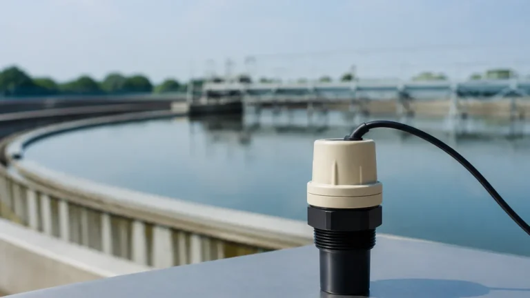
Ultrasonic Meters Natural Gas
Ultrasonic Meters for Natural Gas and Industrial Level Measurement: A Technical Guide
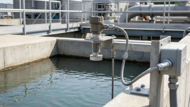
In the landscape of industrial process control, the demand for non-contact, reliable, and cost-effective measurement solutions has led to the widespread adoption of ultrasonic technology. Whether monitoring the volume of liquids in storage tanks or managing the complex flow dynamics within the energy sector, Ultrasonic Level Meters have become a cornerstone of modern automation. This article explores the fundamental principles of ultrasonic technology, its specific application in the context of ultrasonic meters natural gas, and the engineering considerations required for successful deployment.
Understanding the Ultrasonic Measurement Principle
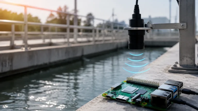
Ultrasonic measurement is based on the "Time of Flight" (ToF) principle. The instrument's transducer emits a high-frequency acoustic pulse—typically ranging from 20 kHz to 80 kHz—directed toward the surface of the medium being measured. This sound wave travels through the air or gas medium, hits the surface of the material, and reflects back to the transducer.
The sensor then calculates the distance based on the time elapsed between the emission of the pulse and the reception of the echo. The formula used is:
Distance = (Speed of Sound × Time) / 2
Because the speed of sound is heavily influenced by the temperature of the medium through which it travels, high-quality Ultrasonic Level Meters incorporate integrated temperature sensors to provide real-time compensation. This ensures that the accuracy of the measurement remains consistent even as ambient or process temperatures fluctuate.
Factors Influencing Sound Velocity
In standard atmospheric conditions, the speed of sound is approximately 344 m/s (1,128 ft/s). However, in industrial environments, particularly those involving pressurized gases or chemical vapors, several variables can alter this velocity:
1. Temperature: Sound speed increases as temperature rises. A 1°C change can result in a 0.17% change in sound speed.
2. Gas Composition: The molecular weight of the gas significantly impacts acoustic transmission. For instance, sound travels differently through methane than it does through nitrogen or air.
3. Pressure: While sound speed is relatively independent of pressure in ideal gases, extreme high-pressure environments can increase gas density, affecting signal attenuation and transducer performance.
Ultrasonic Meters in Natural Gas Applications
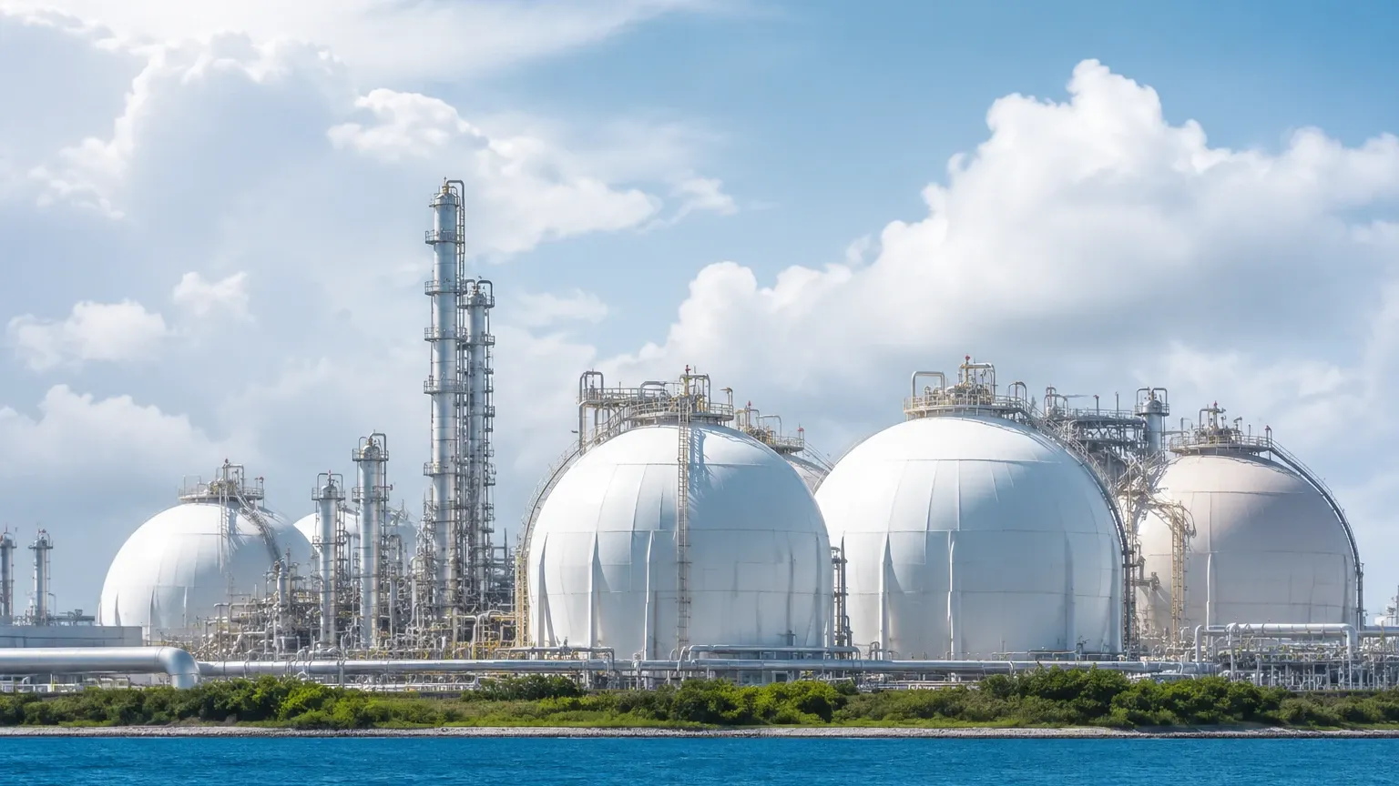
The term ultrasonic meters natural gas typically refers to two distinct but related technologies: ultrasonic flow meters used for custody transfer and ultrasonic level sensors used for managing condensate, wastewater, or chemical additives in gas processing facilities.
Flow Measurement in Natural Gas
In the natural gas industry, ultrasonic flow meters utilize the transit-time difference method. Multiple pairs of transducers send signals upstream and downstream. The difference in travel time is directly proportional to the velocity of the gas flow. These systems are favored for their high accuracy, lack of moving parts, and ability to handle high-volume throughput without causing pressure drops.
Level Measurement in Gas Processing
For level measurement within the natural gas value chain, ultrasonic sensors are frequently deployed in:
* Condensate Tanks: Monitoring the level of hydrocarbon liquids separated from the gas stream.
* Chemical Injection Skids: Ensuring the precise dosage of methanol or glycol used to prevent hydrate formation.
* Produced Water Storage: Managing the byproduct water extracted during gas production.
Welk provides specialized ultrasonic solutions designed to withstand the corrosive and hazardous environments often found in these gas-related applications, ensuring that operators have real-time visibility into their storage capacities.
Key Evaluation Criteria for Selection
Selecting the right instrument requires a thorough understanding of the process environment. Engineers should evaluate the following criteria when comparing ultrasonic solutions:
| Feature | Specification Range | Engineering Consideration |
| :— | :— | :— |
| Measurement Range | 0.3m to 30m (1ft to 98ft) | Ensure the maximum range covers the full tank height plus a safety margin. |
| Accuracy | ±0.25% to ±0.5% of span | Critical for inventory management and billing accuracy. |
| Beam Angle | 5° to 12° | A narrower beam is better for avoiding internal tank obstructions like ladders. |
| Output Signal | 4-20mA, HART, RS485 | Compatibility with existing PLC/SCADA systems is essential. |
| Operating Pressure | Up to 0.3 MPa (3 bar) | Standard ultrasonic level meters are generally limited to near-atmospheric pressures. |
| Protection Rating | IP66, IP67, or IP68 | Determines the sensor's resistance to dust and water ingress. |
Installation Best Practices
Proper installation is the most critical factor in ensuring the long-term reliability of an ultrasonic meter. Failure to follow engineering guidelines often results in "lost echoes" or erratic readings.
1. The Blocking Distance (Dead Zone)
Every ultrasonic transducer has a "blocking distance" or "dead zone" immediately below the sensor face where measurement is impossible. This is the time required for the transducer to stop vibrating after emitting a pulse so it can listen for the return echo. If the liquid level enters this zone, the meter will provide an incorrect reading. Always mount the sensor high enough to ensure the maximum liquid level never enters the dead zone.
2. Positioning and Orientation
* Perpendicularity: The transducer face must be perfectly parallel to the liquid surface. A tilt of even a few degrees can cause the reflected signal to miss the receiver.
* Wall Distance: Do not mount the sensor too close to the tank wall. The acoustic beam spreads as it travels; if it hits the wall, it can create false echoes. A general rule is to keep the sensor at least 200mm (8 inches) away from the wall for every 1 meter of depth.
* Inlet Interference: Avoid mounting the sensor directly above the tank inlet. Falling liquid or turbulence can disrupt the surface and scatter the ultrasonic signal.
3. Avoiding Obstructions
Internal structures such as heating coils, agitators, and ladders can reflect the ultrasonic pulse before it reaches the liquid surface. While many modern Ultrasonic Level Meters feature "false echo suppression" software to ignore these fixed reflections, it is best practice to provide a clear line of sight for the acoustic beam.
Limitations and Risks
While ultrasonic technology is versatile, it is not a universal solution. Engineers must be aware of its physical limitations:
* Vacuum Conditions: Sound waves require a medium (gas or air) to travel. Ultrasonic meters cannot function in a vacuum.
* Heavy Foam: Thick, dense foam on the surface of a liquid can absorb the acoustic pulse, preventing an echo from returning to the sensor. In such cases, radar or hydrostatic transmitters may be more appropriate.
* High Dust or Steam: While light dust is manageable, extremely heavy dust or dense steam can attenuate the signal. High-frequency sensors (higher kHz) are generally more susceptible to attenuation than lower-frequency models.
* Surface Turbulence: Rapidly moving or boiling liquids can scatter the signal. This can often be mitigated by using a stilling well (a vertical pipe that stabilizes the liquid surface).
Frequently Asked Questions (FAQ)
Q: Can ultrasonic meters be used for solids like grain or sand?
A: Yes, but with caveats. Solids do not reflect sound as efficiently as liquids and often have an "angle of repose" that can deflect the signal. Lower-frequency transducers with higher power are typically required for solids.
Q: How does wind affect an outdoor ultrasonic installation?
A: Strong winds can "blow" the acoustic pulse away from the transducer, especially over long distances. For outdoor tanks, using a protective sunshade or a sensor with a stronger signal output is recommended.
Q: What is the difference between a 2-wire and 4-wire ultrasonic meter?
A: A 2-wire meter uses the same pair of wires for both power and the 4-20mA signal, making it easier to install but offering less processing power. A 4-wire meter has separate wires for power (often AC or high-voltage DC) and signal, allowing for higher-power pulses and better performance in challenging environments.
Q: Are ultrasonic meters safe for explosive environments?
A: Many industrial ultrasonic meters are available with ATEX, IECEx, or UL certifications for use in Class I, Div 1 or Div 2 hazardous areas. When dealing with ultrasonic meters natural gas, ensuring the correct hazardous area rating is mandatory.
Conclusion
Ultrasonic technology remains one of the most practical and cost-effective methods for non-contact level measurement in the modern industrial sector. By understanding the physics of sound propagation and adhering to strict installation guidelines, engineers can achieve high levels of accuracy and reliability. Whether you are managing water treatment facilities, chemical storage, or specialized applications involving ultrasonic meters natural gas, selecting a high-quality instrument from a trusted manufacturer like Welk ensures operational efficiency and safety.
For technical assistance in selecting the correct frequency, range, and mounting configuration for your specific application, it is recommended to consult with an application engineer who can provide a customized solution based on your process parameters.