Mass Flow Meter Gas
Mass Flow Meter Gas
In industrial process control, the accurate measurement of gas is a fundamental requirement for safety, efficiency, and fiscal accountability. Unlike liquid measurement, where volume is relatively stable under varying conditions, gases are highly compressible. A change in pressure or temperature significantly alters the volume of a gas, making volumetric flow measurement (such as liters per minute) unreliable without complex compensation. This is where the mass flow meter gas becomes essential. By measuring the mass of the gas molecules directly, these instruments provide a consistent reading regardless of fluctuating process conditions.
For engineers and plant managers, selecting the right technology for gas mass flow is critical. Whether the application involves aeration in water treatment, burner control in chemical processing, or custody transfer in the oil and gas sector, understanding the underlying physics and selection criteria is the first step toward a reliable installation. This guide explores the primary measurement principles, selection parameters, and practical installation considerations for gas mass flow instruments, while also highlighting how these systems integrate with broader industrial automation and level measurement solutions.
Core Measurement Principles for Gas Mass Flow
There are two primary technologies used for direct mass flow measurement of gases: Thermal Mass Flow and Coriolis. Each operates on distinct physical principles and offers specific advantages depending on the application.
Thermal Mass Flow Measurement
Thermal mass flow meters operate based on the heat transfer properties of the gas. The most common design utilizes two Resistance Temperature Detectors (RTDs) immersed in the gas stream. One RTD serves as a reference, measuring the ambient temperature of the gas. The second RTD is heated to a specific temperature above the reference.
As gas flows past the heated sensor, it carries away heat—a process known as the "cooling effect." The amount of heat lost is directly proportional to the mass flow rate of the gas. There are two ways to measure this:
1. Constant Current: The power supplied to the heated sensor is kept constant, and the temperature difference between the two sensors is measured.
2. Constant Temperature Differential: The temperature difference between the sensors is kept constant, and the amount of electrical power required to maintain that difference is measured.
Because the cooling effect depends on the density and velocity of the gas (the mass), the meter provides a direct mass flow reading without needing external pressure or temperature sensors. This technology is particularly effective for low-pressure gas applications and large-diameter pipes where pressure drop must be minimized.
Coriolis Mass Flow Measurement
Coriolis meters utilize the Coriolis effect—an inertial force that acts on objects in motion within a rotating frame of reference. In a Coriolis mass flow meter gas device, the gas flows through one or two vibrating tubes. As the gas moves through the vibrating tube, it causes a slight distortion or "twist" in the tube's vibration.
Sensors located at the inlet and outlet of the tube detect the phase shift in the vibration. This phase shift is directly proportional to the mass flow rate. Coriolis meters are widely considered the "gold standard" for accuracy because they are immune to changes in gas composition, density, and flow profile. However, because gases have much lower density than liquids, Coriolis meters for gas require high velocities or specialized tube designs to generate a measurable signal.
Selection Criteria for Industrial Gas Flow Meters
Choosing between thermal and Coriolis technologies—or other compensated volumetric methods—requires a detailed analysis of the process environment. The following table provides a comparison of the key performance indicators for a typical mass flow meter gas.
Comparison Table: Thermal vs. Coriolis for Gas
| Feature | Thermal Mass Flow | Coriolis Mass Flow |
| :— | :— | :— |
| Typical Accuracy | ±1.0% to ±1.5% of reading | ±0.1% to ±0.5% of reading |
| Turndown Ratio | 100:1 (Excellent for low flow) | 20:1 to 50:1 |
| Pressure Drop | Negligible (Insertion styles) | Moderate to High |
| Gas Composition | Must be known/calibrated | Independent of composition |
| Sensitivity to Moisture | High (Droplets cause spikes) | Low |
| Line Sizes | 15 mm to 6,000 mm | 2 mm to 300 mm |
| Relative Cost | Moderate | High |
Key Evaluation Factors
1. Gas Composition: Thermal meters are calibrated for specific gases (e.g., Nitrogen, Air, Natural Gas). If the gas composition changes significantly, the accuracy of a thermal meter will degrade because the specific heat capacity of the mixture changes. Coriolis meters are generally unaffected by composition changes.
2. Flow Range (Turndown): If the application requires measuring very low flow rates (such as leak detection or pilot lights), thermal mass flow meters are superior due to their high sensitivity at low velocities.
3. Installation Footprint: Thermal insertion meters can be installed in very large ducts or pipes with minimal infrastructure. Coriolis meters are typically larger, heavier, and require more supporting structures.
4. Process Pressure: Coriolis meters perform better at higher pressures where gas density is higher. Conversely, thermal meters are often the only viable mass flow option for very low-pressure or atmospheric systems.
Installation and Engineering Best Practices
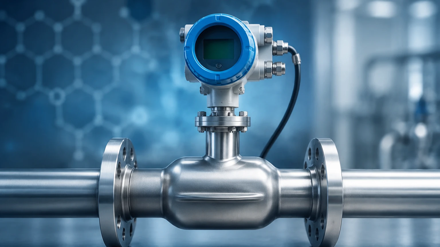
Proper installation is as important as selecting the right technology. Even the most accurate mass flow meter gas will provide erroneous data if the flow profile is disturbed or if the environment is unsuitable.
Straight Pipe Requirements
Thermal mass flow meters are sensitive to the flow profile (the velocity distribution across the pipe). To ensure a fully developed laminar flow, manufacturers typically require a specific length of straight pipe upstream and downstream of the sensor. A common rule of thumb is 15 to 20 diameters (D) upstream and 5D downstream. If the installation site has elbows, valves, or reducers close to the meter, flow conditioners (vanes or perforated plates) may be necessary to stabilize the reading.
Orientation and Mounting
For gas applications, the orientation of the meter can impact its resistance to moisture. If the gas contains potential condensate, the meter should be installed in a vertical pipe with upward flow, or on the top of a horizontal pipe to prevent liquid from pooling on the sensor probes. In thermal meters, the probe must be inserted to the exact center of the pipe (or a specific depth as defined by the manufacturer) to capture the average velocity accurately.
Environmental Considerations
Gas flow meters used in hazardous areas (such as natural gas or hydrogen lines) must have appropriate explosion-proof certifications (ATEX/IECEx). Additionally, vibration can interfere with Coriolis meters. These units should be installed using flexible couplings or rigid supports to isolate the meter from pump or compressor vibrations.
Limitations and Common Risks
While mass flow meters are robust, they are not infallible. Awareness of their limitations prevents costly downtime and measurement errors.
* Moisture and Condensation: In thermal mass flow meters, water droplets hitting the heated sensor can be interpreted as a massive surge in gas flow because water carries away significantly more heat than gas. This results in erratic readings. In such cases, gas dryers or knock-out pots are required upstream.
* Particulate Build-up: In dirty gas applications (like biogas or flare gas), coatings can form on the sensors. In thermal meters, this acts as insulation, slowing the heat transfer and causing the meter to under-report flow. Regular cleaning or the use of "self-cleaning" high-velocity designs is necessary.
* Pressure Limits: While Coriolis meters are excellent for accuracy, they have thin-walled tubes to remain sensitive. High-pressure spikes or water hammer can damage these tubes. Always ensure the meter's pressure rating exceeds the maximum possible system pressure.
Integrating Flow and Level Measurement Systems
In many industrial applications, gas mass flow measurement is one half of a larger control strategy that includes level measurement. For example, in pressurized storage tanks for liquefied gases, operators must monitor both the liquid level and the gas phase flow (boil-off gas or vapor recovery).
Welk, a professional manufacturer of industrial level measurement instruments, provides the critical level data that complements flow systems. In a chemical reactor, for instance, a Welk radar level meter or ultrasonic level sensor ensures the liquid reactants are at the correct volume, while a mass flow meter gas regulates the gaseous catalysts or blanketing gases.
Effective automation requires high-quality data from both types of sensors. For engineers looking to optimize their entire process loop, it is helpful to Review product options and application support to understand how advanced level transmitters—including hydrostatic, magnetic, and radar types—interface with flow control systems to provide a complete picture of tank and vessel status.
Frequently Asked Questions (FAQ)
Q: What is the difference between SCFM and ACFM?
A: ACFM (Actual Cubic Feet per Minute) is the volume of gas flowing at the current pressure and temperature. SCFM (Standard Cubic Feet per Minute) is the volume the gas would occupy at standard conditions (usually 14.7 psia and 60°F). A mass flow meter gas typically outputs in mass units (kg/h) or standardized volumetric units (SCFM/Nm³/h) because mass does not change with pressure.
Q: Do thermal mass flow meters require recalibration if I change the gas type?
A: Yes. Thermal meters rely on the specific heat and thermal conductivity of the gas. If you switch from Nitrogen to Carbon Dioxide, the meter must be reconfigured or recalibrated by the manufacturer to maintain accuracy.
Q: Can a Coriolis meter measure gas at very low pressures?
A: It is difficult. At low pressures, gas density is very low, which means the gas has very little mass per unit volume. This makes it hard for the gas to generate enough force to twist the Coriolis tubes. Thermal mass flow is usually the preferred choice for low-pressure gas applications.
Q: How do I handle flow measurement in pipes larger than 500 mm?
A: For very large pipes, an insertion-style thermal mass flow meter gas is the most cost-effective solution. An inline Coriolis meter for that size would be prohibitively heavy and expensive.
By following these engineering principles and selecting the appropriate technology for the specific gas properties, industrial facilities can achieve high levels of precision in their flow measurement strategies. When paired with reliable level measurement instruments from manufacturers like Welk, these systems form the backbone of modern, efficient industrial automation.