Ultrasonic Level Sensor 0 10v
Understanding the Ultrasonic Level Sensor 0-10V: A Technical Reference for Industrial Integration
In the landscape of industrial automation, precise liquid and solid level monitoring is a cornerstone of process efficiency. Among the various technologies available, non-contact measurement remains a preferred choice for its low maintenance and high reliability. The ultrasonic level sensor 0 10v is a specific configuration of this technology, combining the benefits of ultrasonic time-of-flight measurement with a standardized analog voltage output.
This guide explores the engineering principles, selection criteria, and installation nuances of Ultrasonic Level Meters equipped with 0-10V interfaces, providing a practical framework for system integrators and process engineers.
Measurement Principles of Ultrasonic Technology
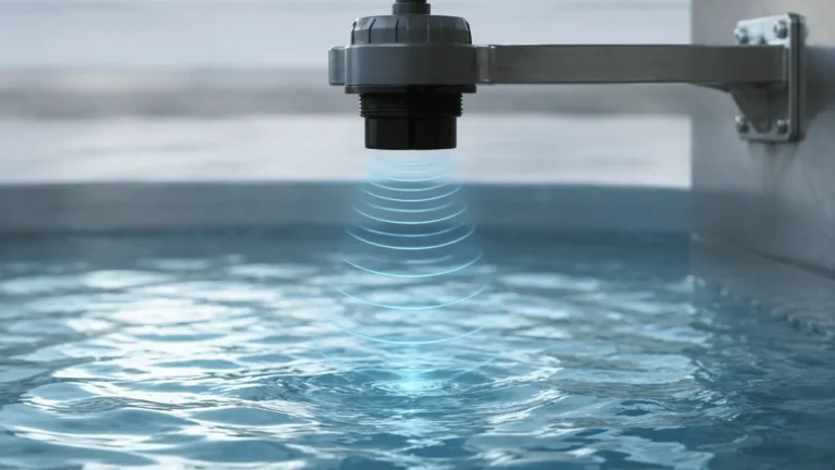
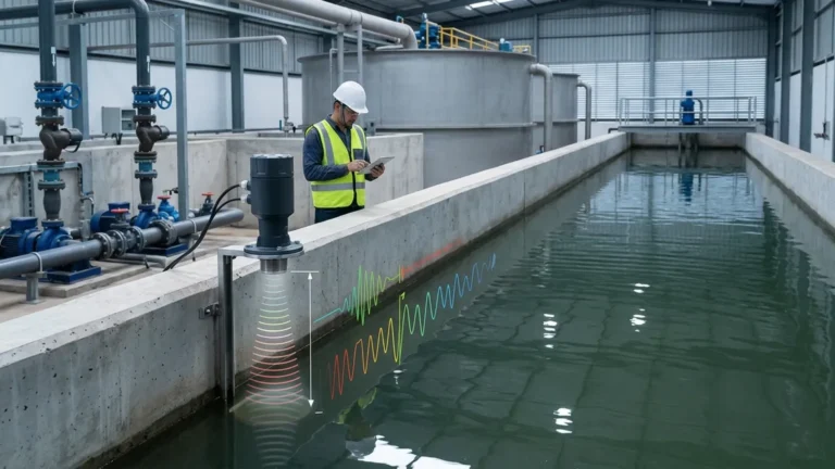
Ultrasonic level measurement operates on the "Time of Flight" (ToF) principle. The instrument’s transducer, typically containing a piezoelectric crystal, emits a high-frequency acoustic pulse. This pulse travels through the air space above the medium, strikes the surface of the material, and reflects back to the sensor.
The Calculation Logic
The sensor’s internal microprocessor calculates the distance between the sensor face and the material surface using the following formula:
Distance = (Speed of Sound × Time Delay) / 2
Because the speed of sound in air is approximately 343 meters per second (at 20°C) but varies significantly with temperature, high-quality instruments like those from Welk include integrated temperature sensors. These sensors provide real-time data to compensate the calculation, ensuring accuracy across varying environmental conditions.
Signal Conversion to 0-10V
Once the distance is determined, the sensor converts this value into a proportional analog signal. In an ultrasonic level sensor 0 10v configuration, 0V typically represents the "Empty" state (maximum distance), while 10V represents the "Full" state (minimum distance/span). This linear relationship allows a Programmable Logic Controller (PLC) or Data Acquisition (DAQ) system to interpret the voltage as a specific level or volume percentage.
Why Choose a 0-10V Analog Output?
While 4-20mA current loops are ubiquitous in heavy industry due to their noise immunity over long distances, the 0-10V signal remains a vital standard in specific sectors, including HVAC, building automation, and small-scale laboratory setups.
1. High Input Impedance Compatibility: Many standard controllers and microcontrollers feature high-impedance analog-to-digital converters (ADCs) that natively accept voltage inputs without requiring external shunt resistors.
2. Simplified Troubleshooting: Voltage signals can be verified quickly using a standard digital multimeter without breaking the circuit loop, which is often necessary for current-based systems.
3. Low Power Consumption: In certain battery-powered or solar-powered remote monitoring applications, voltage-based transmitters can be more energy-efficient than maintaining a constant current loop.
Technical Selection Criteria
Selecting the right ultrasonic level sensor requires a detailed understanding of the application's physical and chemical environment. The following table provides a baseline for evaluating common specifications:
| Feature | Specification Range (Typical) | Impact on Application |
| :— | :— | :— |
| Measuring Range | 0.25m to 15m (0.8ft to 49ft) | Determines the maximum tank height or depth. |
| Dead Zone (Blind Spot) | 0.2m to 0.5m (7.8in to 19.6in) | The area directly below the sensor where measurement is impossible. |
| Accuracy | ±0.25% to ±0.5% of full span | Critical for inventory management and billing. |
| Beam Angle | 6° to 12° | Narrower beams are better for avoiding internal tank obstructions. |
| Output Signal | 0-10V DC (3-wire) | Standardized analog interface for PLCs. |
| Operating Temperature | -20°C to +60°C | Limits use in extreme cryogenic or high-heat processes. |
| Enclosure Rating | IP65 to IP68 | Determines suitability for outdoor or wash-down environments. |
Installation Guidelines and Best Practices
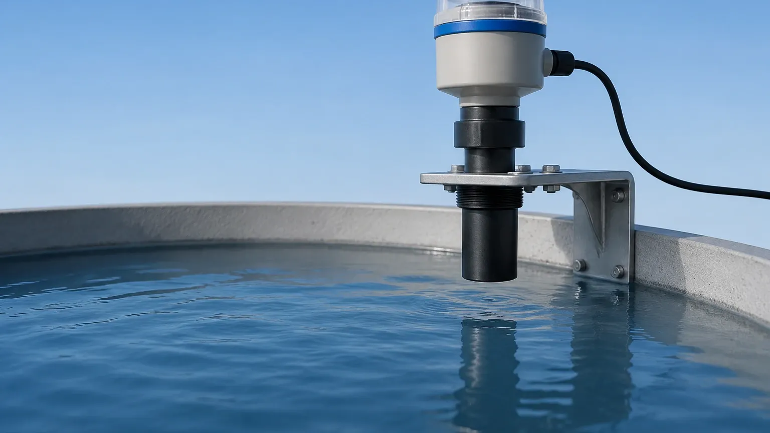
The performance of an ultrasonic level sensor 0 10v is heavily dependent on its physical placement. Incorrect installation is the primary cause of signal instability and false echoes.
1. Managing the Dead Zone
Every ultrasonic sensor has a "dead zone" or "blocking distance" immediately adjacent to the transducer face. In this zone, the crystal is still vibrating from the transmission of the pulse and cannot yet act as a receiver. If the liquid level enters this zone, the sensor will provide erratic readings or fail to detect the surface. Always mount the sensor high enough so that the maximum expected level remains below the dead zone boundary.
2. Avoiding Obstructions and the Beam Angle
The ultrasonic pulse propagates in a cone shape. Any internal tank structures—such as ladders, heating coils, or agitator shafts—that intersect this cone will create "false echoes."
* Calculation: If a sensor has a 10° beam angle and is mounted 5 meters high, the beam diameter at the bottom will be approximately 0.87 meters.
* Solution: Ensure a clear path for the pulse. If obstructions are unavoidable, many modern Ultrasonic Level Meters offer "False Echo Suppression" software to ignore static reflections.
3. Orientation and Surface Conditions
* Perpendicularity: The sensor must be mounted perfectly perpendicular to the liquid surface. A tilt of even a few degrees can cause the reflected signal to bounce away from the transducer, resulting in a "Lost Echo" error.
* Turbulence and Foam: Heavy foam acts as an acoustic absorber, potentially dampening the signal to the point of failure. In cases of extreme turbulence or foam, a stilling well (a vertical pipe that stabilizes the surface) may be required.
Wiring and Signal Integrity for 0-10V Systems
Unlike 4-20mA loops, 0-10V signals are susceptible to voltage drops over long cable runs and electromagnetic interference (EMI).
* Cable Length: It is generally recommended to keep 0-10V signal cables under 15 to 20 meters. For longer distances, the resistance of the wire can cause a measurable drop in voltage, leading to inaccurate readings at the controller.
* Shielding: Use twisted-pair shielded cables to protect the signal from EMI generated by nearby motors, VFDs, or high-voltage power lines. The shield should be grounded at the controller end only to prevent ground loops.
* Power Supply: Most 0-10V sensors are 3-wire devices (Power, Signal, and Common Ground). Ensure the power supply is regulated and capable of handling the sensor's peak current during the pulse transmission.
Limitations of Ultrasonic Level Sensors
While versatile, ultrasonic technology is not a universal solution. Engineers should be aware of the following limitations:
1. Vacuum Applications: Sound waves require a medium (air or gas) to travel. Ultrasonic sensors will not function in a vacuum.
2. High Pressure/High Temperature: Changes in gas density at high pressures significantly affect the speed of sound, often exceeding the compensation capabilities of standard sensors.
3. Heavy Vapor and Dust: Dense steam or heavy dust can scatter the acoustic energy, reducing the effective range and accuracy of the device.
Frequently Asked Questions (FAQ)
Q: Can I use an ultrasonic level sensor for solids like grain or sand?
A: Yes, but with caveats. Solid surfaces are often uneven and absorb more sound than liquids. You typically need to de-rate the sensor's range by 50% and ensure the sensor is positioned to account for the "angle of repose" of the material.
Q: How do I calibrate a 0-10V sensor?
A: Most modern sensors are calibrated via an integrated display, push-buttons, or a digital interface (like RS485). You define the distance that corresponds to 0V (Empty) and the distance that corresponds to 10V (Full).
Q: What happens if the sensor loses the echo?
A: Most units can be configured to "hold" the last valid reading, drive the output to a specific error state (e.g., 11V or 0V), or trigger a digital alarm output.
Q: Is 0-10V better than 0-5V?
A: 0-10V provides better resolution and a higher signal-to-noise ratio than 0-5V, making it the preferred voltage standard in industrial environments where 4-20mA is not used.
Conclusion
The ultrasonic level sensor 0 10v offers a balance of precision, ease of integration, and cost-effectiveness for a wide array of industrial monitoring tasks. By understanding the physics of acoustic reflection and adhering to strict installation protocols regarding dead zones and beam angles, engineers can implement robust level control systems. For applications involving aggressive chemicals, water treatment, or automated storage, Welk’s range of measurement solutions provides the accuracy and durability required for modern industrial standards.