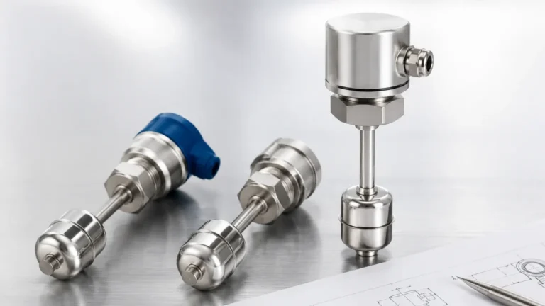
Level Switch Electrical
Level Switch Electrical
In industrial automation and process control, point-level detection serves as a critical safeguard for preventing tank overflows, protecting pumps from dry running, and managing inventory. While the mechanical or physical sensing technology is vital, the level switch electrical configuration determines how effectively the instrument integrates into a facility’s control architecture. A mismatch between the switch’s electrical output and the controller’s input can lead to signal failure, equipment damage, or unsafe operating conditions.
This guide examines the electrical principles behind various Level Switches, detailing output types, wiring configurations, and safety considerations for engineers and technicians.
Measurement Principles and Electrical Conversion
Before selecting an electrical interface, it is essential to understand how different sensing technologies convert physical presence into an electrical state change. Each technology has unique electrical characteristics that influence its compatibility with specific control systems.
Float and Magnetic Level Switches
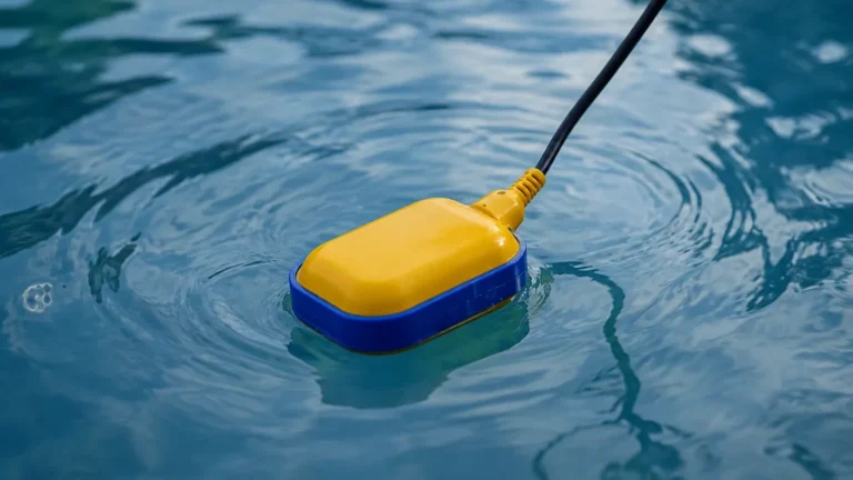
Float-based switches operate on the simplest electrical principle: mechanical contact closure. A permanent magnet within a float moves with the liquid level to actuate a reed switch or a microswitch. From an electrical perspective, these are "dry contacts," meaning they do not require external power to operate the switching mechanism itself. They are highly reliable for simple high/low alarms but are susceptible to contact welding if the electrical load exceeds the switch's rating.
Tuning Fork (Vibrating) Level Switches
Tuning fork switches utilize piezoelectric crystals to vibrate the tines at their natural resonance frequency (typically around 1,200 Hz to 1,400 Hz). When liquid covers the tines, the frequency shifts. The internal electronics detect this frequency change and trigger the output. These units require a continuous power supply (AC or DC) to maintain the vibration, making them "active" electrical devices.
Capacitance Level Switches
Capacitance switches treat the sensor probe and the tank wall (or a reference electrode) as two plates of a capacitor. The liquid acts as a dielectric material. As the level rises, the capacitance of the circuit changes. The level switch electrical circuit includes an oscillator and a detector that converts this capacitance change into a switched output. These are sensitive to the dielectric constant of the medium and require careful grounding to ensure electrical stability.
Ultrasonic and Radar Level Switches
These non-contact or guided-wave technologies use time-of-flight or signal attenuation principles. The electrical assembly includes a transmitter and a microprocessor. Because of the computational power required to process signal echoes, these switches almost always require a 3-wire or 4-wire electrical configuration to provide sufficient current for the electronics.
Primary Electrical Output Types
The choice of output type is dictated by the device being controlled, whether it is a Programmable Logic Controller (PLC), a Distributed Control System (DCS), or a direct motor starter.
1. Relay Outputs (SPDT and DPDT)
Relays are the most versatile electrical outputs. They provide physical isolation between the sensing circuit and the load circuit.
* SPDT (Single Pole Double Throw): Features one common terminal, one normally open (NO) contact, and one normally closed (NC) contact.
* DPDT (Double Pole Double Throw): Essentially two SPDT switches acting in tandem, allowing one switch to control two independent electrical circuits (e.g., an alarm light and a pump starter).
* Advantages: Can handle high voltages (up to 250V AC) and moderate currents (typically 2A to 5A).
2. Transistor Outputs (PNP and NPN)
Common in DC-powered systems, transistors are solid-state switches with no moving parts, offering a virtually unlimited electrical lifespan.
* PNP (Sourcing): The switch connects the load to the positive supply voltage.
* NPN (Sinking): The switch connects the load to the negative (ground) supply voltage.
* Advantages: Extremely fast response times and high reliability in high-cycle applications.
3. Two-Wire (Loop Powered) Outputs
In a 2-wire level switch electrical setup, the device is wired in series with the load. It draws a small "leakage current" to power its internal electronics even when the switch is "off." When triggered, it allows a higher current to flow. This is common in NAMUR-style switches used in hazardous areas.
4. Contactless Electronic Switches (Solid State Relays)
These behave like mechanical relays but use thyristors or MOSFETs. They are ideal for AC loads where mechanical arcing must be avoided, though they often have a higher voltage drop across the switch than mechanical contacts.
Power Supply and Wiring Architectures
Correct wiring is fundamental to the longevity of industrial level instruments. Most Welk level switches are designed for standard industrial voltages, but the architecture varies by model.
| Wiring Type | Description | Best Use Case |
| :— | :— | :— |
| 2-Wire DC | Powered by the signal loop; usually NAMUR or low-current logic. | Hazardous areas with intrinsic safety barriers. |
| 3-Wire DC | Dedicated Positive, Negative, and Signal wires (PNP/NPN). | Standard PLC inputs in factory automation. |
| 4-Wire AC/DC | Two wires for power supply, two for independent relay contacts. | Universal applications where power and load are different voltages. |
Voltage Considerations
Industrial environments typically use 24V DC for control logic due to safety and reduced noise. However, many level switches are available with universal power supplies (e.g., 20V to 250V AC/DC) to accommodate older infrastructure or direct connection to 110V/220V AC mains. It is critical to verify that the supply voltage does not fluctuate beyond ±10% to prevent electronic malfunctions.
Electrical Safety and Hazardous Area Considerations
When level switches are installed in environments containing flammable gases or dust (such as oil and gas or chemical processing), the electrical design must prevent ignition.
Intrinsic Safety (Ex i)
Intrinsically safe level switch electrical systems limit the energy (voltage and current) entering the hazardous area to levels below what is required to ignite an explosive atmosphere. These must be used in conjunction with an isolated safety barrier located in a non-hazardous area.
Flameproof/Explosion-Proof (Ex d)
In this approach, the switch electronics are housed in a heavy-duty enclosure designed to contain an internal explosion and prevent it from propagating to the outside environment. Electrical conduits must be sealed with approved packing glands or compound to maintain the integrity of the enclosure.
Ingress Protection (IP Rating)
Electrical failures are frequently caused by moisture or dust entering the terminal housing. For outdoor or wash-down applications, an IP66 or IP67 rating is standard. This ensures the electrical terminals remain dry even during heavy rain or temporary submersion.

Selection Criteria for Level Switch Electrical Systems
When specifying a level switch, use the following electrical checklist to ensure compatibility:
1. Load Type: Is the load resistive (heaters, lights) or inductive (motors, solenoid valves)? Inductive loads create high back-EMF (electromotive force) when switched off, which can destroy relay contacts. Surge suppressors or snubbers should be used in these cases.
2. Switching Current: Ensure the maximum current rating of the switch exceeds the inrush current of the load. For high-power pumps, use the level switch to trigger a larger contactor rather than wiring the pump directly to the switch.
3. Fail-Safe Logic: Determine if the system needs to be "Fail-Safe High" (output turns off when level is high or power is lost) or "Fail-Safe Low." This is a critical electrical setting for overfill prevention.
4. Cable Run Length: For DC signals, long cable runs (over 100 meters) can experience voltage drops. Ensure the wire gauge (typically 0.75 mm² to 1.5 mm²) is sufficient to maintain the minimum operating voltage at the sensor.
Installation and Maintenance Best Practices
Proper electrical installation extends the life of the instrument and prevents nuisance tripping.
* Conduit Entry: Always install cables with a "drip loop" so that moisture running down the cable does not enter the switch housing. Use high-quality cable glands and ensure unused entries are plugged with certified metal or plastic bungs.
* Shielding and Grounding: For electronic switches (ultrasonic, radar, capacitance), use shielded cables to protect the signal from electromagnetic interference (EMI) caused by nearby Variable Frequency Drives (VFDs) or high-voltage motors. Connect the shield to ground at the controller end only to avoid ground loops.
* Terminal Torque: Ensure terminal screws are tightened to the manufacturer's specified torque. Loose connections increase electrical resistance, causing heat and potential signal intermittent failures.
* Contact Protection: If using a mechanical relay to switch a DC inductive load (like a solenoid), install a flyback diode in parallel with the load to protect the level switch electrical contacts from arcing.
Frequently Asked Questions
Q: Can I use a 24V DC level switch to control a 230V AC pump?
A: Not directly. You must use the 24V DC output of the level switch to energize the coil of an intermediate power relay or contactor rated for 230V AC.
Q: What is the difference between NO and NC in level switches?
A: Normally Open (NO) means the circuit is open when the switch is in its "rest" state (usually empty tank). Normally Closed (NC) means the circuit is closed in the rest state. Most modern switches allow you to invert this logic via a jumper or software setting.
Q: How do I test the electrical function of a level switch?
A: Use a multimeter set to the continuity or resistance scale. For a dry contact switch, manually actuate the float or sensor and check if the circuit opens and closes. For electronic switches, measure the output voltage or current change while simulating a level change.
Q: Why did my reed switch fail in the closed position?
A: This is often caused by "contact welding." If the switch was used to drive a capacitive or inductive load without current limiting, the initial surge current may have fused the small reed contacts together.
Conclusion
Selecting the correct level switch electrical configuration is as important as choosing the right sensing technology. By matching the output type to the control system, adhering to hazardous area requirements, and following robust wiring practices, engineers can ensure reliable point-level detection in any industrial environment. For specific application support or to view technical data sheets, you can Review product options and application support to find the ideal solution for your project requirements.