Level Switch Buhler
Level Switch Buhler
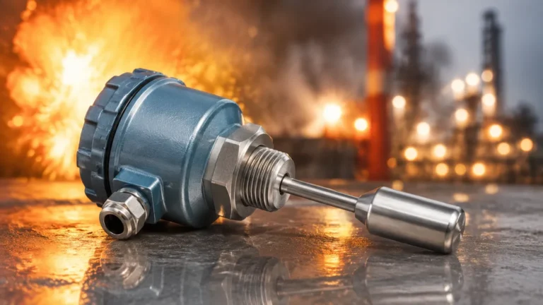
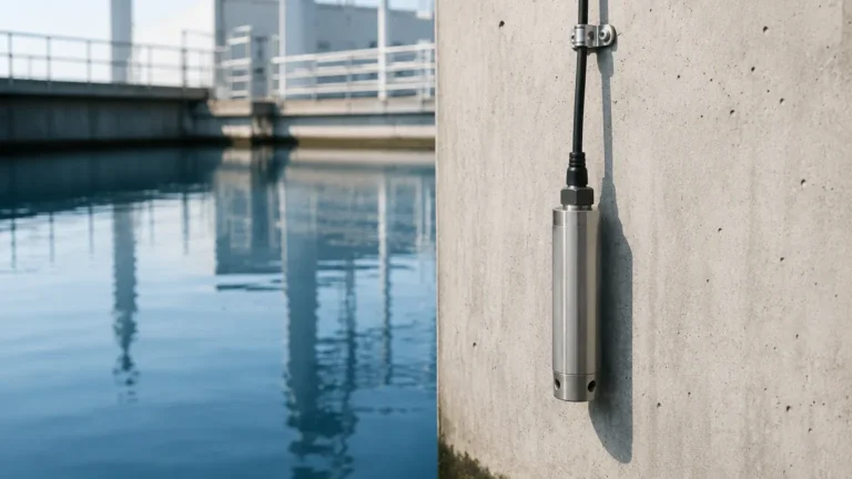
In industrial fluid management, particularly within hydraulic power units and lubrication systems, the precision of point level detection is critical for equipment longevity and operational safety. The term level switch buhler often refers to a specific class of high-reliability level monitoring devices designed to withstand the rigorous demands of hydraulic systems, where temperature fluctuations and oil-based media are standard. These instruments serve as the primary line of defense against pump cavitation, oil starvation, and tank overfills.
Selecting the right level switch requires a deep understanding of the underlying measurement principles, the physical properties of the media, and the specific environmental constraints of the application. This guide explores the technical foundations of these switches, provides selection criteria for engineering professionals, and outlines best practices for installation and maintenance.
Measurement Principles of Magnetic Level Switches
Most industrial level switches, including those categorized under the level switch buhler style, operate on the principle of magnetic buoyancy. This method is favored in B2B industrial applications due to its simplicity, reliability, and the absence of complex electronic components within the sensing zone.
The Magnetic Reed Mechanism
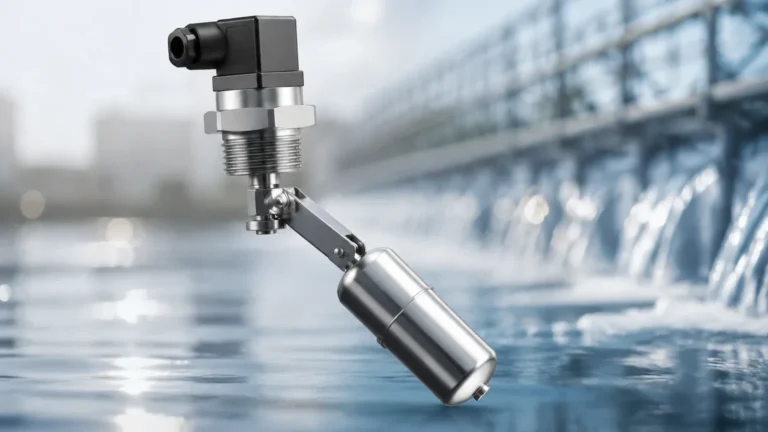
The core of the device consists of a hollow guide tube containing one or more hermetically sealed reed switches. A float, which contains a permanent magnet, slides up and down the guide tube as the liquid level changes. When the float reaches the position of a reed switch, the magnetic field causes the reed contacts to either close (Normally Open – N/O) or open (Normally Closed – N/C).
Because the reed switches are encapsulated in a non-magnetic tube (usually stainless steel or brass), they are protected from the process media. This isolation allows the Level Switches to operate reliably in pressurized tanks and with corrosive or flammable fluids without the risk of electrical sparking in the media.
Integrated Temperature Monitoring
A distinguishing feature of many level switches used in hydraulic systems is the integration of temperature sensors. Since oil viscosity and performance are highly temperature-dependent, these dual-purpose instruments often include a PT100 resistance thermometer or a fixed bimetallic thermal switch at the base of the probe. This allows engineers to monitor two critical process variables through a single tank entry point, reducing potential leak paths.
Technical Specifications and Selection Criteria
When evaluating a level switch buhler for a specific project, engineers must look beyond the basic form factor. The choice of materials and electrical configurations determines the switch's compatibility with the industrial environment.
Material Compatibility
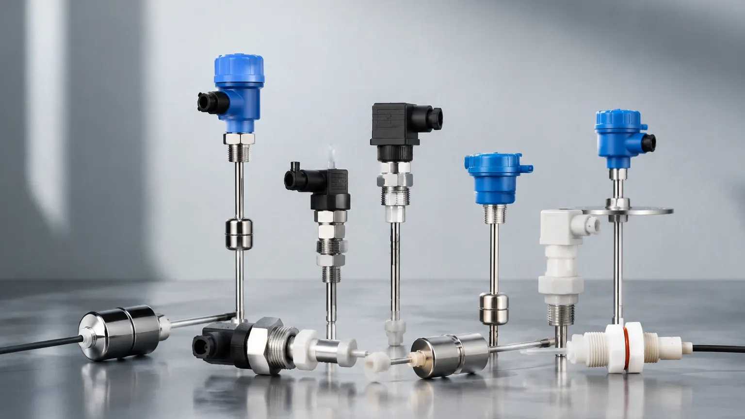
* Stainless Steel (316L/1.4404): Ideal for water treatment, chemical processing, and food-grade applications. It offers superior corrosion resistance and can handle higher pressures.
* Brass: Commonly used in standard hydraulic oil applications. It is cost-effective and provides sufficient durability for non-corrosive lubricants.
* Plastic (PP/PVC/PVDF): Used primarily in aggressive chemical environments where metallic components would degrade rapidly.
Electrical Output Configurations
Industrial level switches typically offer several wiring options to integrate with PLC (Programmable Logic Controller) systems:
1. SPST (Single Pole Single Throw): A simple on/off contact.
2. SPDT (Single Pole Double Throw): Provides a changeover contact, allowing for both high and low alarm signals from a single point.
3. M12 or DIN Connectors: Standardized plug-and-play connections that simplify field wiring and replacement.
Selection Table for Industrial Level Switches
| Feature | Standard Hydraulic Application | Chemical Processing | High-Temperature Systems |
| :— | :— | :— | :— |
| Body Material | Brass or Aluminum | 316 Stainless Steel | 316 Stainless Steel |
| Float Material | NBR or Polyurethane | Stainless Steel | Stainless Steel |
| Max Pressure | 10 bar (145 PSI) | 40 bar (580 PSI) | 25 bar (362 PSI) |
| Temp Range | -20°C to +80°C | -40°C to +120°C | -40°C to +180°C |
| Mounting | G1" or G1 1/2" Thread | Flange (ANSI/DIN) | High-temp Flange |
Application Engineering: Where to Use Level Switch Buhler Styles
These switches are engineered for environments where space is at a premium and reliability is non-negotiable.
Hydraulic Power Units (HPUs)
In HPUs, the level switch monitors the reservoir level. If a hose bursts or a seal fails, the level switch provides an immediate emergency stop signal to the pump, preventing dry running and catastrophic pump failure. The integrated temperature probe ensures the oil remains within the optimal operating window (typically 40°C to 60°C).
Lubrication Systems
Large-scale industrial gearboxes and turbines require constant lubrication. A multi-point level switch can provide a "low level" warning to trigger a refill cycle and a "low-low level" alarm to shut down the machinery if the lubricant falls to a dangerous level.
Industrial Automation
In automated cooling or heating circuits, these switches ensure that the header tanks are sufficiently full to maintain thermal mass and prevent air entrainment in the pumps.
Installation Considerations and Best Practices
To ensure the longevity of a level switch, proper installation is as important as the initial selection. Engineers should adhere to the following guidelines:
1. Vertical Alignment: Magnetic float switches must be mounted vertically (within ±30° of the vertical axis) to ensure the float moves freely along the guide tube. Excessive tilt can cause friction and sticking.
2. Avoid Magnetic Interference: Since the switch operates via magnetic fields, it should be installed away from high-power electric motors, transformers, or large ferrous structures that could distort the magnetic field and cause false triggering.
3. Turbulence Protection: In tanks with high agitation or near-inlet pipes, the float may bounce, leading to "chatter" in the electrical signal. In such cases, a stilling well (a perforated pipe surrounding the probe) should be used to dampen the liquid surface movement.
4. Wiring and Protection: Use shielded cables for long runs to the PLC to prevent electromagnetic interference (EMI). Ensure the cable entry is sealed to prevent moisture ingress, which can lead to terminal corrosion.
Limitations and Operational Constraints
While highly reliable, magnetic level switches have specific limitations that must be considered during the design phase:
* Viscosity Limits: Extremely thick or highly viscous fluids (above 100 cSt) can impede the movement of the float. For such media, ultrasonic or radar-based level sensors may be more appropriate.
* Metallic Contaminants: In systems where the fluid may contain metallic particles (e.g., machining coolant), these particles can adhere to the magnetic float, eventually increasing its weight and causing it to sink or stick.
* Coating and Scaling: If the media tends to crystallize or leave heavy deposits, the float may become stuck to the guide tube. Regular inspection intervals are required in these applications.
Maintenance and Troubleshooting
A proactive maintenance schedule for level switches typically includes a semi-annual functional test. This is performed by manually lifting the float (if the tank is empty) or using a secondary magnet to trigger the reed contacts while observing the PLC input status.
Common Troubleshooting Steps
* Switch fails to trigger: Check for debris blocking the float or verify the continuity of the reed switch using a multimeter. If the reed switch is "stuck" closed despite the magnet being moved away, it may have been damaged by a current surge.
* Intermittent signals: Often caused by loose wiring at the terminal block or moisture inside the connection head. Ensure all seals are intact and connections are torqued correctly.
* False Alarms: Usually the result of turbulence or foam. Consider installing a stilling well or adjusting the PLC debounce timer to ignore very short signal transitions.
Frequently Asked Questions (FAQ)
Q: Can a level switch buhler be used in hazardous (Ex) zones?
A: Yes, provided the specific model is certified (e.g., ATEX or IECEx) and is used in conjunction with an intrinsically safe barrier. The reed switch itself is a simple contact, but the housing and wiring must meet zone-specific requirements.
Q: What is the difference between a level switch and a level transmitter?
A: A level switch provides a discrete (on/off) signal at specific points. A level transmitter provides a continuous output (e.g., 4-20mA or 0-10V) representing the exact level across the entire sensing range. For simple high/low alarms, a switch is more cost-effective.
Q: How do I choose between a Normally Open (N/O) and Normally Closed (N/C) contact?
A: This depends on the safety logic. For low-level alarms, a Normally Closed contact is often preferred (the circuit opens when the level drops). This provides a "fail-safe" feature; if a wire breaks, the system will trigger an alarm, alerting the operator to the fault.
Q: Can these switches handle high-pressure tanks?
A: Standard models are usually rated for 10-16 bar. Specialized versions with reinforced guide tubes and high-buoyancy floats can handle pressures up to 40 bar or higher. Always verify the pressure rating on the manufacturer's data sheet.
Conclusion
Selecting a level switch buhler style device requires balancing technical requirements with environmental realities. Whether managing hydraulic oil levels or monitoring industrial lubricants, understanding the magnetic reed principle and the importance of material compatibility ensures a robust installation. For engineers seeking reliable, accurate, and cost-effective point level detection, exploring a wide range of Level Switches is the first step toward optimizing process safety and efficiency. By adhering to strict installation standards and regular maintenance protocols, these instruments provide years of trouble-free service in the most demanding B2B industrial applications.