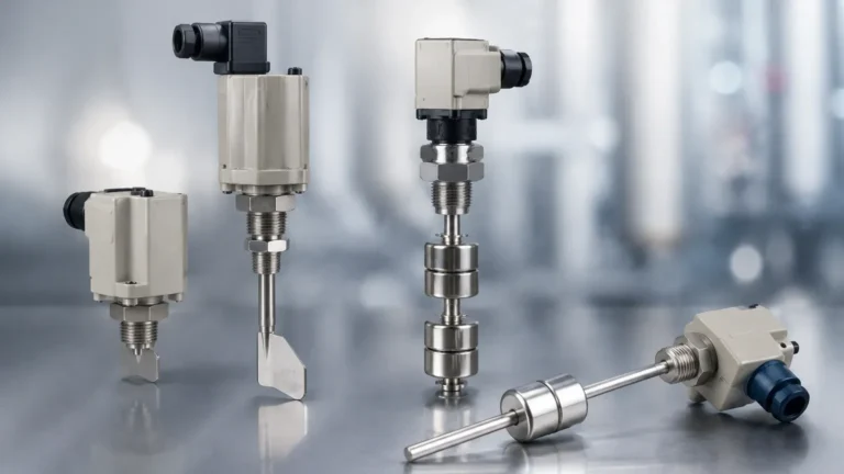
Side Mounted Liquid Level Switches
Side Mounted Liquid Level Switches
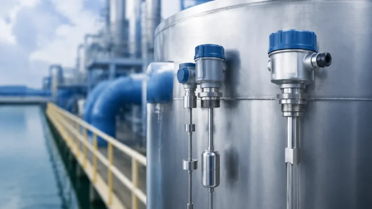
In industrial process control, point level detection serves as a critical fail-safe and automation trigger. Side mounted liquid level switches are among the most common instruments used to prevent tank overflows, protect pumps from dry-running, and manage automated filling cycles. Unlike top-mounted sensors that require vertical headspace, side-mounted units are installed through the wall of a vessel, making them ideal for tanks with limited overhead clearance or where internal obstructions prevent vertical access.
Selecting the right side mounted liquid level switch requires an understanding of the underlying measurement principles, the chemical compatibility of the materials, and the specific physical constraints of the application. This guide provides a technical overview of the technologies available, selection criteria, and installation best practices for engineering and maintenance professionals.
Measurement Principles of Side Mounted Level Switches
Side-mounted switches operate on several distinct physical principles. The choice of technology depends heavily on the liquid's viscosity, density, and whether it contains solids or creates coatings.
1. Float-Operated Switches (Mechanical and Magnetic)
Float switches are the most traditional form of side-mounted level detection. They rely on buoyancy to move a float as the liquid level rises or falls.
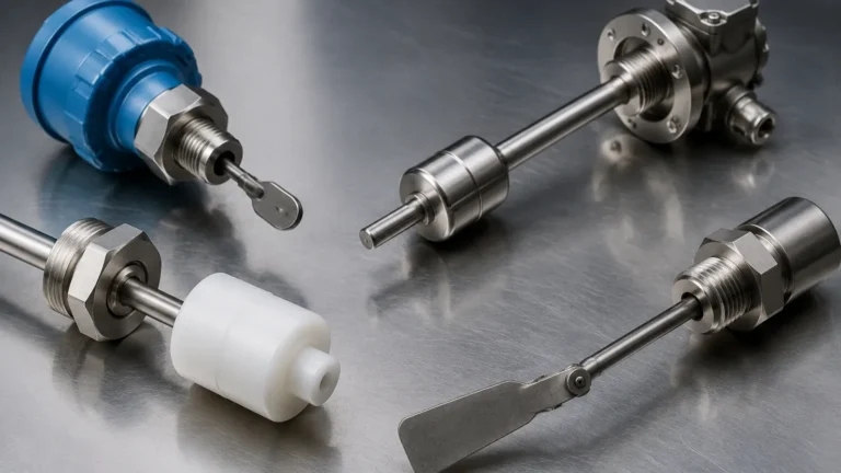
* Mechanical Hinge: In a basic mechanical side-mounted switch, the float is attached to a hinged lever. As the liquid rises, the float moves upward, pivoting the lever to actuate a microswitch. These are simple and cost-effective but have moving parts that can wear over time.
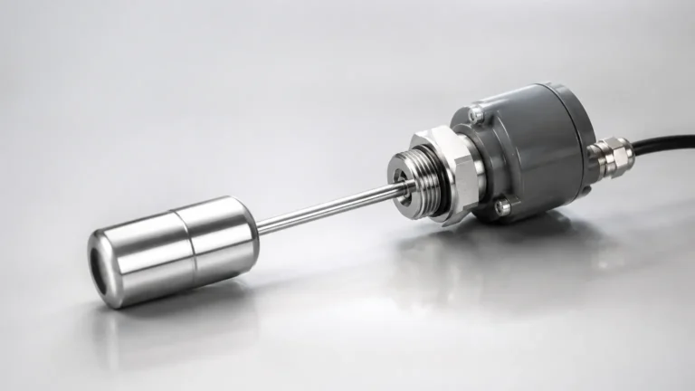
* Magnetic Coupling: A more robust version uses a magnetic float. As the float rises with the liquid, it moves a magnet near a reed switch or a magnetic linkage located outside the process seal. This design eliminates the need for a direct mechanical link between the wetted parts and the electrical switch, significantly reducing the risk of leaks.
2. Vibrating Tuning Fork Switches
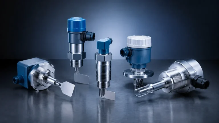
Vibrating level switches use piezoelectric crystals to energize a tuning fork at its natural resonant frequency in air. When the fork is submerged in a liquid, the frequency changes or the vibration is damped. An internal electronic circuit detects this shift and triggers the switch output. Because they do not rely on buoyancy, tuning fork switches are less affected by changes in liquid density or flow turbulence.
3. Optical Level Switches
Optical switches utilize an infrared LED and a light receiver housed within a prism-shaped tip. When the tip is in air, the infrared light reflects back to the receiver. When the tip is immersed in liquid, the light is refracted into the medium, causing the receiver to sense a drop in intensity. These are extremely compact and have no moving parts, though they can be sensitive to coating or highly reflective bubbles.
4. Capacitance Level Switches
These switches measure the change in electrical capacitance between the probe and the tank wall (or a reference electrode). As liquid replaces air around the probe, the dielectric constant changes, triggering the switch. These are effective for a wide range of liquids but require calibration to the specific dielectric constant of the media.
Key Evaluation Criteria for Selection
Choosing the correct instrument involves more than just matching a thread size. Engineers must evaluate the following parameters to ensure long-term reliability.
Media Characteristics
* Specific Gravity (SG): For float-based Level Switches, the float must be less dense than the liquid. Most standard floats require an SG of at least 0.7. For lighter hydrocarbons, specialized low-density floats are required.
* Viscosity: Highly viscous liquids can impede the movement of mechanical floats or cause "bridging" on tuning forks. Vibrating forks are generally better for viscous media than mechanical floats, provided the viscosity does not exceed the manufacturer’s damping limits (typically up to 10,000 mm²/s).
* Chemical Compatibility: The wetted parts—usually Stainless Steel (304 or 316L), Polypropylene (PP), or PTFE—must be resistant to the process fluid. PP is common for water and mild acids, while 316L is the standard for oil, gas, and food-grade applications.
Process Conditions
* Pressure: Side-mounted switches are subject to the full hydrostatic head and internal tank pressure. Standard plastic units may only handle 1–3 bar, while heavy-duty stainless steel magnetic switches can withstand 40 bar or higher.
* Temperature: Standard electronics are often rated up to 80°C. For high-temperature applications (up to 200°C or more), switches with extended necks or high-temperature seals are necessary to protect the internal switching elements.
Practical Selection Table
| Technology | Best For | Limitations | Typical Pressure Range |
| :— | :— | :— | :— |
| Magnetic Float | Clean liquids, water, oils | Susceptible to scaling/solids | Up to 40 bar |
| Vibrating Fork | Slurries, aerated liquids | Not for very high viscosity | Up to 64 bar |
| Optical | Compact spaces, OEM | Not for coating liquids | Up to 20 bar |
| Capacitance | Corrosive chemicals | Requires calibration | Up to 25 bar |
Installation Considerations and Best Practices
Correct installation is paramount for the accuracy and safety of side-mounted liquid level switches. Because these units penetrate the side of the tank, the integrity of the seal and the orientation of the device are the primary concerns.
1. Orientation and Alignment
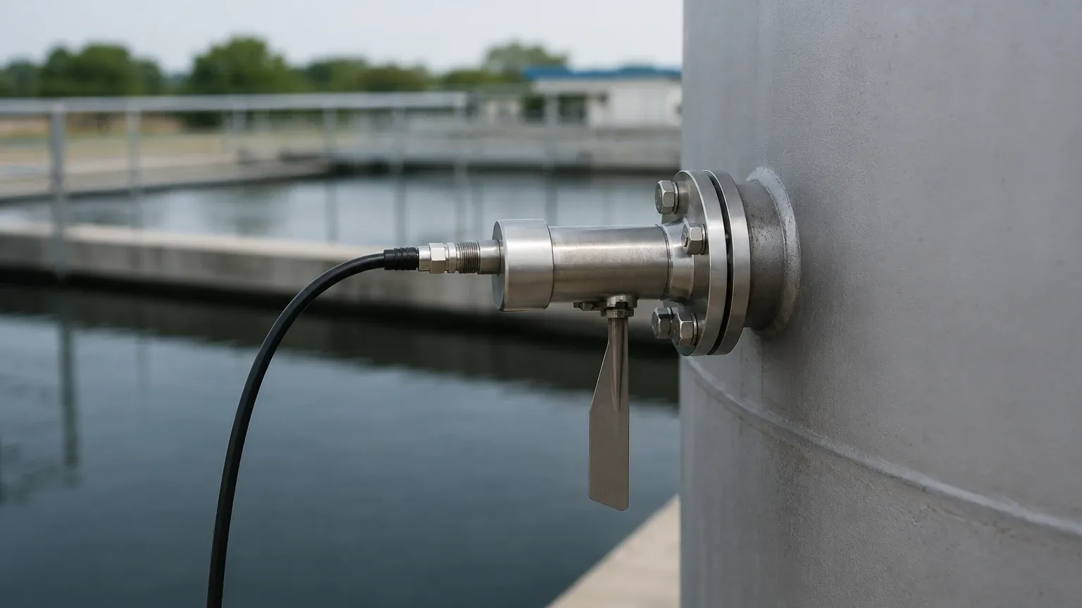
Most side-mounted float switches must be installed horizontally. If the switch is tilted, the hinge mechanism may bind, or the float may not have enough buoyancy to overcome the internal friction. For tuning forks, the orientation of the "paddles" is important; in heavy or viscous liquids, the forks should be oriented so that the liquid can easily drain off them when the level drops, preventing false "wet" readings.
2. Avoiding Turbulence and Dead Zones
Switches should not be installed directly in the path of an inlet flow or near an agitator. The resulting turbulence can cause "chatter" (rapid cycling of the switch), which can damage pumps or contactors. If installation near an inlet is unavoidable, a baffle or stilling well should be used to protect the sensing element.
3. Seal Selection
Common mounting options include NPT or G threads and various flange sizes (e.g., DN25, ANSI 1"). It is essential to use compatible sealants or gaskets. For high-pressure applications, flanged connections are generally preferred over threaded connections for better leak prevention and easier maintenance access.
4. Wiring and Housing
In outdoor or wash-down environments, ensure the housing has an appropriate IP rating (IP65 or higher). For hazardous areas involving flammable vapors, explosion-proof (Ex d) or intrinsically safe (Ex i) housings are mandatory. Always loop the wiring downward before it enters the cable gland to prevent moisture from running along the cable and into the housing (a "drip loop").
Limitations and Common Risks
While side-mounted switches are versatile, they are not universal solutions. Engineers should be aware of the following risks:
* Build-up and Coating: If the liquid tends to crystallize or leave a thick residue, mechanical floats can become stuck in the "up" or "down" position. Vibrating forks can also fail if the material builds up between the tines. In these cases, non-contact radar or ultrasonic sensors might be more appropriate.
* Magnetic Interference: Magnetic float switches can be affected by strong external magnetic fields or by the presence of ferrous particles in the liquid. Ferrous debris can stick to the magnetic float, increasing its weight and changing its buoyancy profile.
* Mechanical Fatigue: In applications with frequent level changes or high vibration, the hinge point of a mechanical switch is a potential point of failure. Regular inspection of the pivot pin and float integrity is recommended.
Frequently Asked Questions (FAQ)
Q: Can a side-mounted switch be used for continuous level measurement?
A: No. Side-mounted switches are point-level devices. They provide a binary signal (on/off) at a specific height. For continuous measurement (e.g., 0–100% full), a radar, ultrasonic, or hydrostatic transmitter should be used.
Q: What is the difference between Normally Open (NO) and Normally Closed (NC) in this context?
A: This refers to the state of the electrical switch when the tank is empty (or the liquid is below the switch level). Most side-mounted switches are "reversible," meaning you can flip the float or change the wiring to switch between NO and NC logic depending on whether you are protecting against overflow or dry-running.
Q: How do I test the switch without filling the tank?
A: Many magnetic side-mounted switches allow for manual actuation via an external lever or by moving a magnet near the housing to simulate the float's rise. For tuning forks, a "test" button is often included on the electronic module to simulate a damped state.
Conclusion and Confirmation Steps
Before finalizing a purchase or installation plan for side mounted liquid level switches, project teams should confirm the following data points:
1. Chemical Resistance: Verify that the housing and seal materials are compatible with the process fluid at maximum operating temperatures.
2. Mounting Space: Ensure there is enough external clearance for the housing and internal clearance for the float's arc of travel.
3. Electrical Load: Confirm that the switch contact rating (Amps/Volts) matches the requirements of the PLC input or the pump motor starter it will control.
4. Maintenance Access: Ensure the switch is installed at a height and location where it can be inspected or replaced without requiring a total plant shutdown or specialized scaffolding.
By following these engineering guidelines, facilities can ensure reliable point level detection that protects both equipment and personnel from the risks associated with improper liquid level management.