Stilling Well for Radar Level Transmitter
Stilling Well for Radar Level Transmitter: Engineering Design and Application Guide
In industrial process control, achieving a stable and accurate level measurement is often challenged by environmental factors such as surface turbulence, foam, and complex tank internals. For engineers utilizing non-contacting Radar Level Meters, the integration of a stilling well (also known as a still pipe or surge pipe) is a common and effective solution to these challenges.
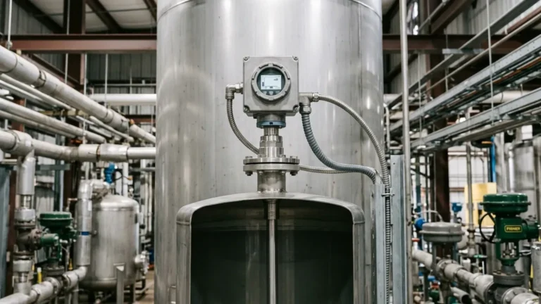
A stilling well acts as a vertical guide that isolates the liquid surface from the rest of the tank's dynamics, providing a controlled environment for the radar signal. This guide explores the measurement principles, design specifications, and installation requirements for a stilling well for radar level transmitter applications.
Measurement Principles in Stilling Wells
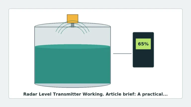
To understand why a stilling well is used, one must first understand the fundamental operation of radar level measurement. Radar transmitters emit high-frequency electromagnetic pulses (typically in the 6GHz, 26GHz, or 80GHz range). These pulses travel at the speed of light, reflect off the surface of the medium, and return to the sensor. The device calculates the distance based on the Time-of-Flight (ToF) or Frequency Modulated Continuous Wave (FMCW) shift.
The Waveguide Effect
When a radar transmitter is mounted on a stilling well, the metal pipe functions as a waveguide. In free-space applications, the radar beam spreads in a cone shape, and signal strength decreases according to the inverse-square law. However, inside a conductive metal pipe, the electromagnetic waves are confined. This confinement results in several technical advantages:
1. Signal Concentration: The energy is focused within the pipe, significantly increasing the amplitude of the return echo. This is particularly beneficial for liquids with low dielectric constants (Dk), such as hydrocarbons or liquefied gases.
2. Elimination of Parasitic Reflections: Internal obstructions like agitators, heating coils, or structural reinforcements can cause "false echoes" in an open tank. The stilling well physically blocks these obstructions from the radar's path.
3. Surface Stabilization: In tanks with heavy agitation or boiling surfaces, the stilling well provides a calm, representative surface for the radar to track.
Why Use a Stilling Well for Radar Level Transmitters?
While modern 80GHz radar technology features narrow beam angles that can often avoid obstructions, a stilling well remains a critical component in specific scenarios:
* Low Dielectric Media: If the liquid has a dielectric constant below 1.9, the reflected signal in free space may be too weak to distinguish from background noise. The waveguide effect of the pipe boosts this signal.
* Heavy Foam: While radar can struggle with thick, dense foam, a stilling well allows the liquid level to rise inside the pipe while the foam remains largely outside, or is compressed into a thinner, more manageable layer.
* Turbulent Surfaces: In reactors or mixing tanks, the surface is often too chaotic for a consistent reflection. The pipe acts as a mechanical filter, dampening waves.
* Limited Installation Space: If the only available nozzle is close to the tank wall, a stilling well prevents the beam from hitting the wall and generating interference.
Engineering Design and Selection Criteria
Designing a stilling well for radar level transmitter use requires precision. A poorly designed pipe can introduce more errors than it solves. The following table summarizes the key selection parameters for industrial applications.
Table 1: Selection Criteria for Stilling Wells
| Parameter | Specification | Engineering Rationale |
| :— | :— | :— |
| Pipe Diameter | 50mm to 200mm (2" to 8") | Must match the radar antenna size. Smaller pipes (50-80mm) are common for high-frequency radars. |
| Material | 304/316L Stainless Steel | Provides a smooth, conductive internal surface and prevents corrosion buildup. |
| Wall Thickness | Schedule 10 or 40 | Must be structurally sound but minimize the weight on the tank nozzle. |
| Vent Holes | 3mm to 10mm diameter | Located at the top (above max level) to equalize pressure and prevent air pockets. |
| Inner Surface | Ra < 0.8 µm (Smooth) | Minimizes signal scattering and prevents product buildup. |
| Joint Type | Internal Flush / Butt-weld | Prevents signal reflections from internal ridges or gaps at pipe segments. |
Venting and Drainage
A stilling well must have at least one vent hole near the top, above the maximum liquid level. This ensures that the pressure inside the pipe matches the tank pressure, allowing the liquid level inside the pipe to move freely with the tank level. Without proper venting, a vacuum or pressure pocket can cause a "level lag," leading to inaccurate readings. For liquids that may trap air, additional smaller holes along the length of the pipe may be necessary to ensure representative density and level.
Installation Considerations
Correct installation is paramount to the performance of Radar Level Meters used within stilling wells. Engineers should adhere to the following checklist:
1. Vertical Alignment: The pipe must be installed as vertically as possible. A deviation of more than 0.5° to 1° can cause the radar signal to bounce multiple times against the pipe walls, weakening the signal and increasing noise.
2. Internal Smoothness: Any weld seams must be ground smooth on the inside. A ridge as small as 1mm can create a significant false echo that the radar might mistake for the liquid level.
3. Hole De-burring: When drilling vent or equalization holes, ensure that no burrs remain on the inside of the pipe. All holes should be drilled at an angle or cleaned thoroughly.
4. Bottom Clearance: The pipe should generally extend to the bottom of the tank, leaving a small gap (approx. 20mm to 50mm) for flow, or it should have a 45° cut at the bottom to prevent sediment accumulation from blocking the pipe.

Limitations and Risks
Despite their benefits, stilling wells are not a universal solution. Engineers must be aware of the following limitations:
* Product Buildup and Clogging: In applications involving viscous liquids, waxes, or substances that crystallize (e.g., bitumen or heavy crude), the product can coat the inner walls of the pipe. This reduces the effective diameter and can eventually "bridge" the pipe, causing the radar to lock onto a false level.
* Corrosion and Scaling: If the internal surface becomes pitted or scaled due to chemical attack, the radar signal will scatter, leading to a loss of echo or decreased accuracy.
* Non-Conductive Pipes: Plastic (PVC/PP) pipes do not act as waveguides. While they can be used to calm the surface, they do not provide the signal-boosting benefits of a metal pipe and may cause complex refraction issues.
Information for International Buyers
When sourcing a stilling well for radar level transmitter or the radar units themselves, procurement teams should confirm the following technical details with the manufacturer:
1. Pipe Inner Diameter (ID): Radar firmware is often optimized for specific pipe IDs. Provide the exact ID and pipe schedule to the supplier.
2. Flange Specification: Ensure the mounting flange of the radar matches the flange on the stilling well (e.g., ASME B16.5, EN 1092-1).
3. Process Compatibility: Confirm that the pipe material and gaskets are compatible with the chemical properties and temperature of the process media.
4. Radar Frequency: 80GHz radars are increasingly preferred for stilling wells due to their ability to ignore smaller imperfections in the pipe, but 26GHz remains a standard for many larger-diameter well applications.
Frequently Asked Questions (FAQ)
Q: Can I use a stilling well with a Guided Wave Radar (GWR)?
A: Yes, but it is often redundant. GWR already uses a probe (coaxial or single rod) to guide the signal. A stilling well is most commonly used with non-contacting radar to provide the waveguide effect.
Q: How do I handle a stilling well in a tank with a floating roof?
A: In floating roof tanks, the stilling well (often called a gauge pole) passes through the roof. The radar is mounted at the top. Special care must be taken to ensure the pipe is perforated correctly to allow the liquid to enter while maintaining structural integrity.
Q: Should the stilling well be grounded?
A: Yes. For safety and to ensure the waveguide properties, the metal stilling well must be electrically bonded to the tank and the radar housing.
Q: What is the maximum length for a stilling well?
A: Technically, stilling wells can exceed 30 meters. However, maintaining verticality and internal smoothness over such lengths is challenging. For very deep tanks, high-power FMCW radars are recommended.
Conclusion
A stilling well for radar level transmitter is a powerful tool for optimizing level measurement in difficult industrial environments. By concentrating the radar signal and shielding the measurement area from foam and turbulence, it ensures reliable data for process automation. However, the success of the installation depends on rigorous attention to the pipe's internal geometry, material selection, and vertical alignment. For complex applications, consulting with a specialized manufacturer like Welk ensures that the instrumentation and the guiding hardware are perfectly matched for the specific process conditions.