2 Position Limit Switch
2 Position Limit Switch
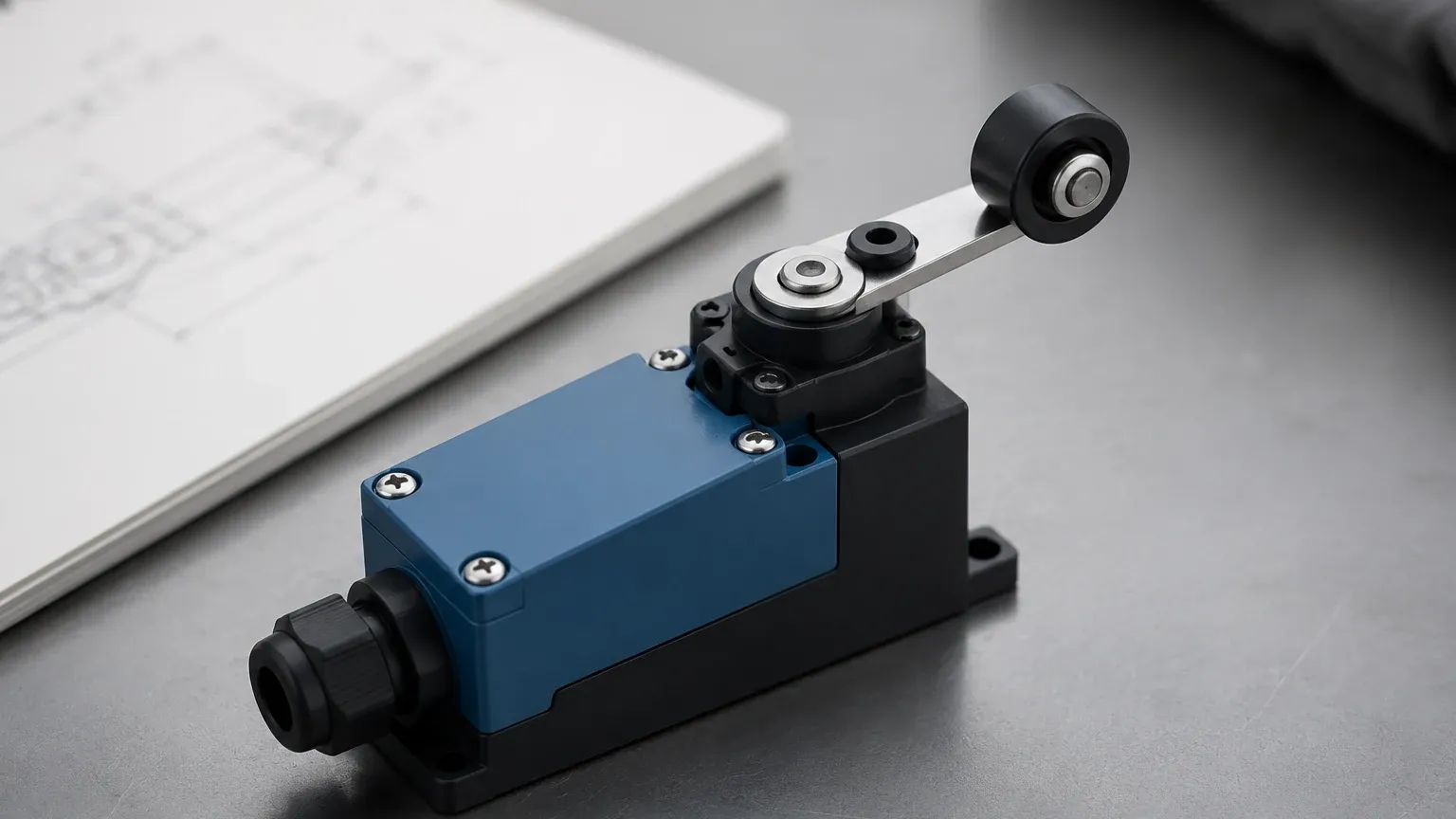
In the landscape of industrial automation and process control, the 2 position limit switch serves as a critical sentinel for safety and efficiency. Whether it is monitoring the travel of a mechanical arm or detecting the presence of liquid in a storage tank, these devices provide the binary feedback necessary for programmable logic controllers (PLCs) to make real-time decisions. In fluid management and bulk solids handling, these instruments are more commonly categorized under the broader umbrella of Level Switches, where they function as point-level detectors to prevent overflows or dry-run conditions.
Understanding the mechanics, electronic principles, and selection criteria for a 2 position limit switch is essential for maintenance engineers and system integrators. This guide explores the technical nuances of these devices, their integration into level measurement systems, and the practical considerations for industrial deployment.
Measurement Principles of Point-Level Switches
A 2 position limit switch operates on a simple premise: it changes its electrical state (from open to closed, or vice versa) when a specific physical condition is met. In level measurement, this condition is the contact with or proximity to a process medium. The underlying technology determines how the switch perceives this change.
Mechanical Actuation
Mechanical limit switches utilize physical contact. A lever, plunger, or rod is moved by the force of the material or a float. This movement triggers a microswitch inside the housing. These are prized for their simplicity and the fact that they do not require power to operate the sensing element itself, though the contact circuit requires a signal voltage.
Vibratory (Tuning Fork) Principle
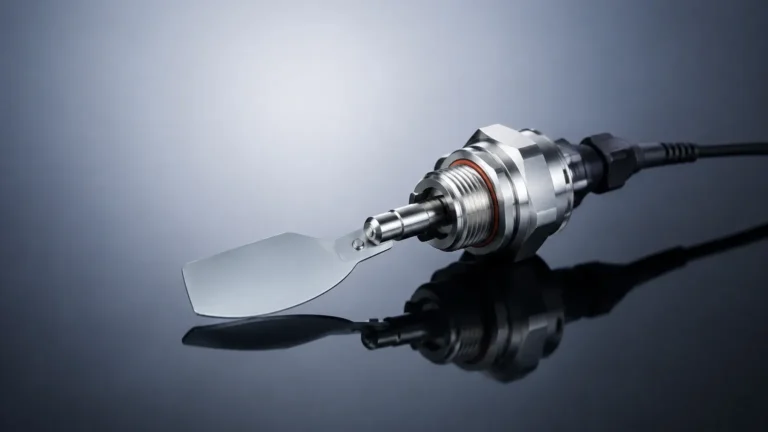
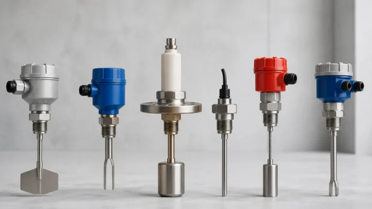
Commonly used in liquid and solid level detection, a tuning fork sensor vibrates at its natural resonant frequency in free air. When the medium covers the fork, the frequency shifts or the vibration is dampened. The internal electronics detect this change and flip the switch position. This method is highly resistant to changes in pressure, temperature, and foam.
Capacitive Sensing
Capacitive switches measure the change in electrical capacitance between the sensor probe and the tank wall (or a reference electrode). Since different materials have different dielectric constants, the presence of a medium significantly alters the capacitance, triggering the 2 position limit switch output.
Ultrasonic and Optical Principles
Non-contact or gap-style ultrasonic switches use sound waves to detect the presence of a medium. When the gap between a transmitter and receiver is filled with liquid, the signal strength changes. Optical switches rely on the refraction of light within a prism; when liquid covers the prism, the light is refracted into the medium rather than reflected back to the sensor.
The Role of 2 Position Limit Switches in Industrial Systems
In most B2B industrial applications, a 2 position limit switch is utilized for one of three primary functions: high-level alarm (overfill protection), low-level alarm (pump protection), or intermediate position control.
1. Overfill Prevention: The switch is installed at the top of a vessel. When the material reaches the sensor, the switch changes state to close an inlet valve or stop a feed pump. This is a critical safety layer in chemical and oil and gas industries.
2. Dry-Run Protection: Installed near the bottom of a tank or inside a pipe, the switch ensures that a pump does not operate without fluid, which could lead to overheating and mechanical failure.
3. Interface Detection: Specialized versions can detect the boundary between two immiscible liquids, such as oil and water, acting as a limit switch that triggers when the denser medium reaches the probe.
Technical Comparison of Switching Technologies
Selecting the right technology requires balancing the physical properties of the medium against the environmental conditions of the plant. The following table provides a comparison of common point-level technologies used as 2 position limit switches.
| Technology | Suitable Media | Pressure Range | Temp. Range | Main Advantage |
| :— | :— | :— | :— | :— |
| Float Switch | Clean Liquids | Up to 40 bar (580 psi) | -40 to 150°C | Low cost, simple installation |
| Tuning Fork | Liquids, Powders | Up to 64 bar (928 psi) | -50 to 250°C | Reliable, no calibration needed |
| Capacitive | Solids, Slurries | Up to 100 bar (1450 psi) | -40 to 200°C | No moving parts, handles buildup |
| Conductive | Conductive Liquids | Atmospheric | -20 to 100°C | Extremely economical |
| Mechanical Limit | Moving Parts/Gates | N/A | -40 to 120°C | High current switching capacity |
Selection Criteria for Engineering Specifications
When specifying a 2 position limit switch for a project, engineers must look beyond the basic "on/off" function. The following parameters are critical for long-term reliability:
Wetted Materials and Chemical Compatibility
The sensor components in contact with the medium must withstand corrosion. Common materials include 316L stainless steel, PTFE (Teflon), and PP (Polypropylene). For highly aggressive acids, specialized coatings or exotic alloys like Hastelloy may be required.
Electrical Output and Load
Standard industrial switches offer various output types:
* Relay (SPDT/DPDT): Ideal for switching high-current loads directly, such as small motors or solenoids.
* Transistor (PNP/NPN): Used for high-speed switching and direct interfacing with PLC digital inputs.
* Two-wire AC/DC: Simplifies wiring by mimicking a traditional mechanical contact in series with the load.
Process Connections
The physical mounting of the switch must match the vessel's ports. Common connections include NPT or BSP threads (e.g., 1/2", 1", 1.5") and various flange sizes (DIN or ANSI). For hygienic applications in food and beverage, Tri-Clamp connections are standard to ensure there are no crevices where bacteria can grow.
Environmental Ratings
Industrial environments are often harsh. A 2 position limit switch should carry an IP rating (e.g., IP66 or IP67) for dust and water ingress protection. In hazardous areas where explosive gases or dust are present, ATEX, IECEx, or UL hazardous location certifications are mandatory.
Installation Guidelines and Best Practices
Correct installation is as important as the selection of the device itself. Failure to follow engineering best practices can lead to false triggers or premature sensor failure.
Orientation and Positioning
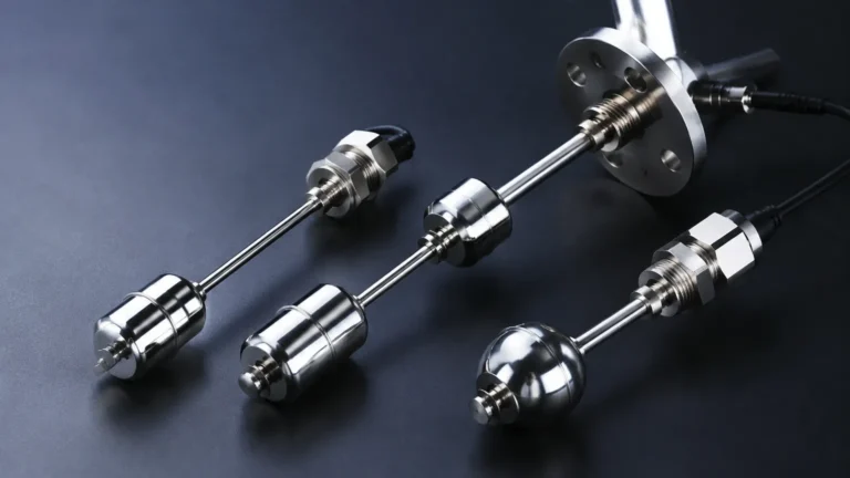
* Top Mounting: Usually reserved for long-stem float switches or ultrasonic sensors. Ensure the "dead zone" of the sensor is accounted for so it doesn't miss high-level events.
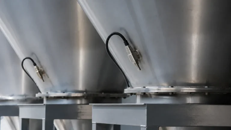
* Side Mounting: Common for tuning forks and capacitive switches. The device should be tilted slightly downward (approx. 20 degrees) if the medium is a powder or granulate to prevent material from accumulating on the sensing element.
* Avoid Turbulence: Do not install a level switch directly in the path of an incoming material stream. The force of the falling liquid or solid can damage the probe or cause intermittent switching.
Wiring and Shielding
To prevent electromagnetic interference (EMI) from VFDs (Variable Frequency Drives) and heavy motors, use shielded cables for electronic switches. Ensure the cable entry points are facing downward to prevent moisture from traveling along the cable and into the housing (the "drip loop" method).
Calibration and Testing
While many modern tuning fork and float switches are "plug-and-play," capacitive and ultrasonic switches often require calibration. This involves setting the sensitivity threshold to distinguish between the actual material and any coating or foam that might adhere to the probe.
Limitations and Common Risks
Despite their utility, 2 position limit switches are not universal solutions. Engineers should be aware of the following limitations:
* Material Buildup: In sticky or viscous applications, material can coat the sensor. If the switch cannot ignore this buildup (a feature known as "active shield" in capacitive sensors), it may stay in the "on" position indefinitely.
* Mechanical Wear: Float switches and mechanical limit switches have moving parts that eventually fatigue. In high-cycle applications, solid-state (non-moving) sensors like tuning forks are preferred.
* Turbulence and Foam: Rapidly agitating liquids can cause "chatter," where the switch rapidly flips between states. This can be mitigated by using a switch with a built-in time delay (typically 1 to 5 seconds) or a stilling well.
* Specific Gravity Limits: Float-based switches rely on buoyancy. If the liquid's density changes significantly (e.g., due to temperature fluctuations), the float may no longer trigger at the correct level.
Frequently Asked Questions (FAQ)
Q: Can a 2 position limit switch be used for continuous level measurement?
A: No. A 2 position switch only provides information about a single point. For continuous tracking (e.g., 0% to 100% volume), a level transmitter (radar, ultrasonic, or hydrostatic) is required.
Q: What is the difference between a "Normally Open" (NO) and "Normally Closed" (NC) switch?
A: A Normally Open switch does not complete the circuit until it is actuated. A Normally Closed switch completes the circuit in its resting state and breaks it when actuated. For safety applications (like high-level alarms), NC is often preferred because a wire break will trigger the alarm, providing a fail-safe mechanism.
Q: How do I handle switching for high-temperature steam applications?
A: High-temperature applications require switches with cooling fins or remote electronics. Magnetic level gauges with external switches are also a popular choice, as the switch is isolated from the process temperature by the gauge chamber.
Q: Is it possible to test the switch without filling the tank?
A: Many electronic Level Switches feature a manual test button or a magnetic test point on the housing. This allows maintenance personnel to simulate an alarm state to verify the logic of the control system without needing to manipulate the process level.
Conclusion
The 2 position limit switch remains a cornerstone of industrial process safety. By providing a definitive signal at critical points, these devices protect equipment, personnel, and the environment. When selecting a switch, engineers must carefully evaluate the chemical compatibility, physical state of the medium, and the electrical requirements of the control architecture. Whether choosing a rugged mechanical switch for a heavy-duty valve or a sophisticated tuning fork for a chemical reactor, understanding the fundamental principles ensures a reliable and long-lasting installation.