Level Failed No More Possible Switches
Level Failed No More Possible Switches
In industrial automation and process control, the integrity of level detection is paramount for safety, environmental protection, and operational efficiency. When a control system triggers an alert such as "level failed no more possible switches," it signifies a critical state where the redundancy or the primary sensing logic for a vessel has been exhausted. This scenario often arises in high-integrity pressure protection systems (HIPPS) or safety instrumented systems (SIS) where multiple Level Switches are employed to provide a voted logic output (e.g., 2-out-of-3 or 1-out-of-2).
Understanding the root causes of sensor failure and the principles behind point-level detection is essential for process engineers to resolve these errors and prevent future downtime. This guide examines the mechanical and electronic principles of level switching, selection criteria for high-reliability environments, and the engineering steps required when a system indicates that no further switching options are available.
Measurement Principles of Level Switches
Before addressing system-level failures, it is necessary to understand how different technologies detect the presence or absence of a medium. Each technology has specific strengths and failure modes that contribute to the overall reliability of the measurement loop.
Vibrating (Tuning) Fork Switches
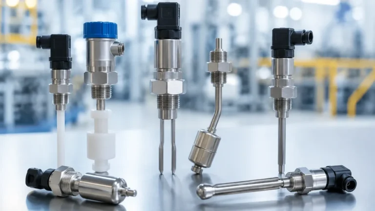
Vibrating fork switches utilize piezoelectric crystals to energize a metal fork at its natural resonant frequency. When the fork is immersed in a liquid or solid, the frequency shifts. This change is detected by the internal electronics and converted into a switching signal. These are highly reliable because they are generally unaffected by flow, turbulence, bubbles, or foam.
Float and Magnetic Level Switches
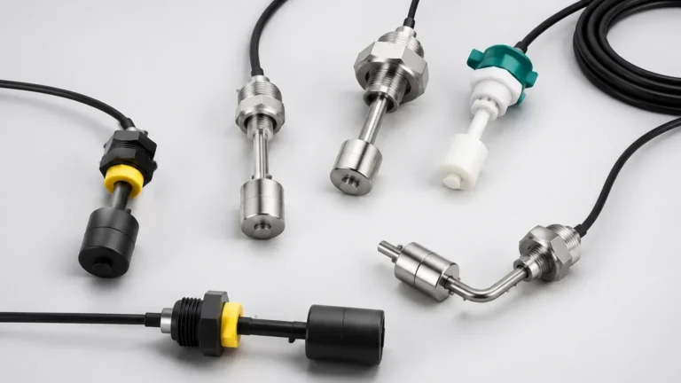
Float switches operate on the principle of buoyancy. A float containing a magnet moves with the liquid level along a stem. When the magnet reaches a specific point, it actuates a reed switch or a microswitch. While simple and cost-effective, these are mechanical devices subject to wear, sticking due to debris, or damage from high-velocity inflows.
Capacitance Level Switches
These sensors treat the probe and the tank wall (or a reference electrode) as two plates of a capacitor. As the medium displaces air, the dielectric constant changes, altering the capacitance. These switches are effective for powders and liquids but can be sensitive to coating or buildup on the probe, which may lead to a "false positive" or a failed state.
Ultrasonic and Optical Switches
Ultrasonic switches use high-frequency sound waves that travel across a gap; when liquid fills the gap, the signal strength changes. Optical switches use an infrared LED and a prism; when liquid covers the prism, the light is refracted into the liquid rather than reflected back to the sensor. Both are non-mechanical but can be affected by heavy coating or extreme turbidity.
Analyzing the "Level Failed No More Possible Switches" State
The error "level failed no more possible switches" typically occurs in complex control architectures where the software manages a pool of physical sensors. If a process requires three switches for a 2-out-of-3 (2oo3) voting logic to ensure a safe shutdown, and two of those sensors return a fault code or an out-of-range signal, the system can no longer perform its safety function.
Common reasons for this total failure include:
1. Common Cause Failure (CCF): Using the same technology for all redundant points. For example, if three float switches are installed in a high-viscosity fluid that hardens, all three may stick simultaneously.
2. Power Supply Issues: A failure in the 24V DC loop powering a bank of switches.
3. Logic Configuration Errors: The PLC or DCS may be programmed with a limit on the number of bypassed or failed inputs allowed before a total system lockout occurs.
4. Environmental Extremes: Sudden pressure spikes or temperature excursions exceeding the hardware limits of all installed units.
Selection Criteria for Industrial Level Switches
To prevent a "no more possible switches" scenario, engineers must select hardware based on the specific chemical and physical properties of the process. The following table provides a comparison of common technologies used in Welk industrial solutions.
| Technology | Typical Media | Max Pressure (Approx.) | Max Temp (Approx.) | Key Advantage | Limitation |
| :— | :— | :— | :— | :— | :— |
| Tuning Fork | Liquids, Powders | 64 bar | 150°C – 250°C | No calibration needed | Sensitive to heavy buildup |
| Float Switch | Clean Liquids | 40 bar | 180°C | Simple, No power needed | Moving parts can jam |
| Capacitance | Liquids, Solids | 100 bar | 200°C+ | High pressure/temp | Requires calibration |
| Conductivity | Conductive Liquids | 20 bar | 150°C | Very low cost | Only for conductive media |
| Optical | Clear Liquids | 50 bar | 125°C | Compact size | Sensitive to coating |
Installation Considerations to Ensure Reliability
Proper installation is the primary defense against premature failure. Even the most advanced Level Switches will fail if environmental factors are ignored.
Turbulence and Agitation
In tanks with agitators, switches should be installed in a stilling well or away from the direct path of the blades. Vibrating forks should be oriented so that the blades are parallel to the flow to minimize resistance and prevent material accumulation between the tines.
Nozzle Length and Dead Zones
Ensure that the sensing element extends fully into the vessel. If a switch is mounted in a long nozzle, material may become trapped (bridging), causing the switch to remain in the "on" state even when the vessel is empty. For viscous liquids, flush-mounted or extended-probe versions are preferred.
Electrical Integrity
Use shielded cables to prevent electromagnetic interference (EMI) from variable frequency drives (VFDs) or heavy motors. Ensure that the cable glands are properly tightened and pointed downwards (using a drip loop) to prevent moisture ingress into the housing, which is a leading cause of electronic failure.

Troubleshooting a Failed Level System
When the system reports that no more switches are available, follow this diagnostic hierarchy:
1. Check Physical State: Manually verify the level in the tank using a secondary method (like a sight glass or manual dip).
2. Verify Loop Power: Measure the voltage at the sensor terminals. A drop below 18V DC can cause intermittent failures in electronic switches.
3. Inspect for Coating: Remove the sensors to check for buildup. If a tuning fork is caked in dried material, it will report a frequency shift equivalent to being submerged.
4. Test Output Logic: Use a multimeter to check if the switch's contact (SPDT/DPDT) or transistor output (PNP/NPN) matches the expected state. If the hardware is functioning but the PLC shows a failure, the issue lies in the wiring or the I/O card.
5. Evaluate Redundancy Logic: If the software has locked out the process, check the "reset" conditions. Some safety systems require a manual acknowledgement once a minimum number of switches are restored to health.
Limitations of Point-Level Switches
While highly effective for overfill protection and pump control, point-level switches have inherent limitations:
* Single Point Detection: They provide no information about the level between the mounting points. For continuous monitoring, radar or ultrasonic transmitters are required.
* Material Specificity: A switch calibrated for water may not function correctly in oil or foam without adjustment.
* Mechanical Wear: In float-based systems, the pivot points and reed switches have a finite cycle life (often between 100,000 and 1,000,000 operations).
Frequently Asked Questions (FAQs)
Q: Can I use a vibrating fork switch for aerated liquids?
A: Generally, yes. Vibrating forks are designed to ignore bubbles and foam. However, if the aeration is so extreme that the density of the medium drops significantly below the switch's minimum density rating (e.g., < 0.5 g/cm³), the frequency shift may not be sufficient to trigger the switch.
Q: What does "fail-safe" mean in the context of level switches?
A: Fail-safe refers to the state the switch assumes upon loss of power. For high-level alarms, a fail-safe switch should be "normally closed" so that if a wire breaks or power is lost, the circuit opens, triggering an alarm as if the tank were full.
Q: How often should level switches be proof-tested?
A: In safety-critical applications, proof-testing intervals are determined by the required Safety Integrity Level (SIL). For standard industrial applications, an annual physical check and functional test (raising the level to trigger the switch) is recommended.
Q: Why would all three switches in a redundant system fail at once?
A: This is usually due to a "Common Cause Failure." Examples include a shared power supply failure, a process temperature exceeding the limits of all sensors simultaneously, or a chemical attack that corrodes the wetted parts of all sensors because they are made of the same material.
By selecting the appropriate technology and adhering to rigorous installation standards, engineers can minimize the risk of a "level failed no more possible switches" error, ensuring that the process remains safe and productive. For more detailed specifications on various sensing technologies, engineers should consult technical datasheets and application notes specific to their industry requirements.