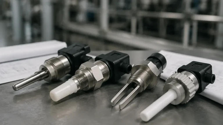
Level Switch 61f Gp N
Level Switch 61f Gp N
In the landscape of industrial automation, maintaining precise control over liquid levels is fundamental to operational safety and efficiency. Among the various technologies used to achieve this, the level switch 61f gp n represents a widely adopted solution for conductive liquid applications. This device, categorized under the broader family of Level Switches, operates on the principle of liquid conductivity to trigger automated processes such as pump control, alarm activation, and tank level regulation.
Understanding the technical nuances, installation requirements, and operational limits of the 61f gp n is essential for plant engineers and system integrators. This guide provides a comprehensive technical overview of the device, its measurement principles, and practical considerations for industrial implementation.
Measurement Principle: Conductive Level Sensing
The level switch 61f gp n is a floatless level controller that utilizes the electrical conductivity of the liquid being measured. Unlike mechanical float switches that rely on buoyancy, this electronic switch uses electrodes as sensors.
How the Conductivity Circuit Works
When the liquid level rises and makes contact with the stainless steel electrodes, an electrical circuit is completed between the electrodes. The liquid acts as a conductor, allowing a low-voltage alternating current (AC) to flow from the controller through the liquid and back. The controller detects this current and activates an internal electromagnetic relay.
Key aspects of this principle include:
* AC Voltage Application: To prevent electrolysis and electrode corrosion, these switches typically use a low AC voltage (often 8V or 24V AC) across the electrodes rather than direct current (DC).
* Sensitivity Threshold: The controller is designed to recognize a specific range of electrical resistance. If the liquid's resistance is lower than the device's threshold, the switch triggers. This makes it ideal for water, sewage, and various chemical solutions, but unsuitable for non-conductive liquids like oils or deionized water.
* Electrode Configuration: A standard setup usually involves three electrodes: a common electrode (longest), a low-level electrode, and a high-level electrode. This configuration allows for differential control, preventing "relay chatter" caused by surface turbulence.
Technical Specifications of the 61f gp n
The 61f gp n is characterized by its compact, plug-in design, typically utilizing an 8-pin or 11-pin circular socket. This modularity allows for rapid replacement and maintenance without disturbing the field wiring.
| Feature | Specification |
| :— | :— |
| Supply Voltage | 100, 110, 120, 200, 220, or 240 VAC (50/60 Hz) |
| Inter-electrode Voltage | 8 VAC |
| Power Consumption | Approx. 3.5 VA maximum |
| Response Time | Operating: 80 ms max; Releasing: 160 ms max |
| Control Output | 5 A at 250 VAC (Resistive load) |
| Ambient Temperature | -10°C to 55°C (14°F to 131°F) |
| Ambient Humidity | 45% to 85% RH |
| Insulation Resistance | 100 MΩ minimum (at 500 VDC) |
Selection Criteria and Technology Comparison
Choosing the correct switch depends on the physical properties of the media and the environmental conditions of the tank. While the level switch 61f gp n is excellent for conductive liquids, other technologies may be required for complex applications.
Comparison Table: Level Measurement Technologies
| Technology | Media Compatibility | Best Use Case | Limitations |
| :— | :— | :— | :— |
| Conductive (61f gp n) | Conductive liquids (water, acids) | General water supply/drainage | Not for oils or pure water; scaling issues |
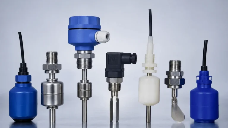
| Float Switches | Most liquids | Simple high/low alarms | Moving parts can jam; prone to buildup |
| Ultrasonic Sensors | Liquids and solids | Non-contact continuous measurement | Affected by foam, steam, and heavy dust |
| Radar Level Meters | Almost all media | High-precision, high-pressure tanks | Higher initial investment cost |
| Capacitive Switches | Conductive and non-conductive | Small tanks, powders | Requires calibration for different media |
Practical Installation Considerations
Proper installation of the 61f gp n and its associated electrodes is critical for long-term reliability. Engineers must account for electrode length, spacing, and environmental interference.
Electrode Assembly
1. Electrode Holders: Use specialized holders (such as the PS-3S or BF series) to secure the electrodes and provide insulation from the tank wall, especially in metal tanks.
2. Electrode Material: Standard electrodes are 304 or 316 stainless steel. For highly corrosive chemical environments, titanium or Hastelloy electrodes should be specified.
3. Separators: If electrodes exceed 1 meter (approx. 3.3 feet) in length, ceramic or plastic separators should be used every 500 mm to 1000 mm to prevent the electrodes from touching due to liquid movement.
Wiring and Logic
The 61f gp n is commonly used for two primary functions: automatic water supply and automatic drainage.
* Automatic Water Supply: The relay is wired to start a pump when the level drops below the low-level electrode (E2) and stop the pump when it reaches the high-level electrode (E1). The common electrode (E3) must always remain submerged or grounded to the tank.
* Automatic Drainage: The logic is reversed. The pump starts when the liquid reaches E1 and stops when it falls below E2. This prevents the pump from running dry while ensuring the tank does not overflow.
Surge and Interference Protection
In industrial environments with large motors or variable frequency drives (VFDs), electrical noise can interfere with the low-voltage electrode circuit. It is recommended to:
* Use shielded cables for electrode wiring if the distance between the controller and the tank exceeds 50 meters.
* Ensure the controller is properly grounded.
* Avoid running electrode lines parallel to high-power AC lines.
Limitations and Prohibitions
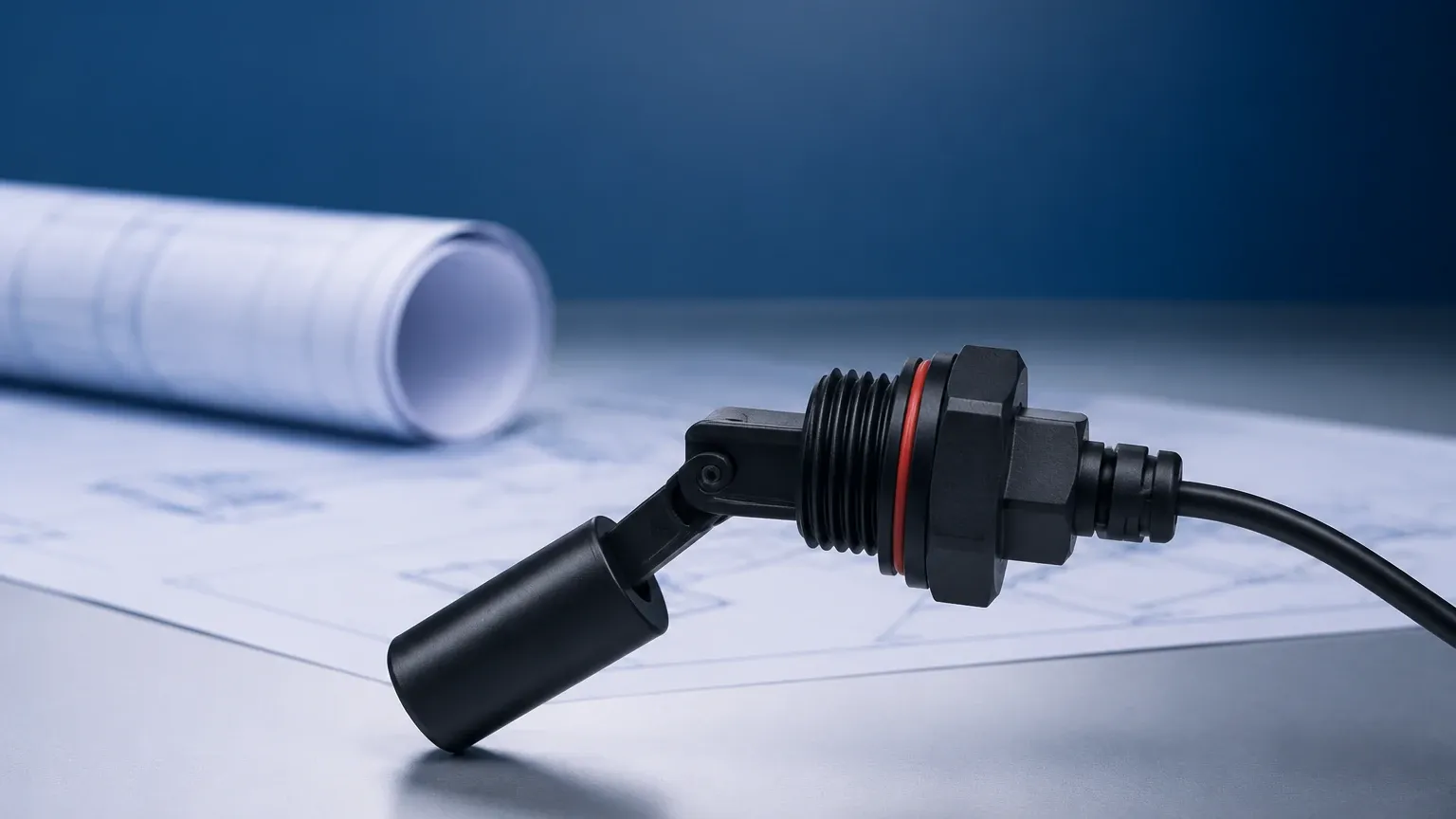
While the level switch 61f gp n is a robust industrial tool, it is not a universal solution. The following limitations apply:
1. Non-Conductive Media: It cannot detect oils, fats, pure distilled water, or dry solids. For these applications, ultrasonic or radar-based Level Switches are more appropriate.
2. Coating and Scaling: If the liquid creates a non-conductive scale or film on the electrodes (such as calcium buildup or oil film), the circuit will fail to complete, and the switch will not trigger.
3. Turbulent Surfaces: While the E1-E2-E3 configuration provides a deadband to prevent rapid cycling, extreme turbulence may still cause intermittent signals. In such cases, a stilling well (a pipe surrounding the electrodes) should be installed.
4. Pressure and Temperature: The controller itself must be mounted in a controlled environment (control panel). Only the electrodes and holders are exposed to the process. Ensure the electrode holders are rated for the specific tank pressure and temperature.
Troubleshooting Common Issues
The Pump Does Not Start
* Check Power Supply: Verify that the correct voltage is reaching the controller terminals.
* Electrode Continuity: Inspect electrodes for heavy corrosion or non-conductive coating. Clean the electrodes with an abrasive cloth if necessary.
* Wiring Check: Ensure the common electrode (E3) is properly connected and reaching the lowest point required.
The Relay "Chatters" (Rapid On/Off)
* Sensitivity Adjustment: Some variants of the 61f series have sensitivity adjustments. If the liquid has high resistance, the sensitivity may need to be increased.
* Surface Waves: If the liquid surface is highly agitated, the high-level electrode may intermittently lose contact. Increase the distance between the high (E1) and low (E2) electrodes or install a stilling well.
The Pump Does Not Stop
* Short Circuit: Check if the electrodes are touching each other or the metal tank wall. Ensure separators are intact.
* Moisture in Holder: Check the electrode holder for moisture or condensation that might be creating a conductive path between the electrode terminals.
Frequently Asked Questions (FAQ)
Q: Can I cut the electrodes to a custom length?
A: Yes, stainless steel electrodes are typically designed to be cut to the specific depths required by your application. Ensure the ends are clean after cutting.
Q: What is the maximum distance between the controller and the electrodes?
A: For standard models, the distance should generally not exceed 100 meters. For distances beyond this, high-sensitivity models or shielded wiring are required to compensate for cable capacitance.
Q: Is the 61f gp n suitable for sewage?
A: Yes, but it is highly recommended to use "sensing bands" or specialized non-clogging electrodes rather than thin rods, as debris in sewage can cause false triggers or bridge the gap between electrodes.
Q: Can I use this switch for high-temperature steam boilers?
A: The controller must be in a cool panel, and you must use high-temperature ceramic-insulated electrode holders specifically rated for boiler service.
Conclusion
The level switch 61f gp n remains a cornerstone of conductive liquid level control due to its simplicity and reliability. By understanding the underlying conductivity principles and adhering to strict installation guidelines regarding electrode placement and wiring, engineers can implement a cost-effective solution for a wide range of industrial water and chemical management tasks. For applications involving non-conductive media or requiring non-contact measurement, exploring advanced Level Switches and radar technologies is recommended to ensure optimal process performance.