Level Switch Controller
Level Switch Controller
In the landscape of industrial automation, point level detection serves as a critical safeguard and control mechanism for tanks, sumps, and process vessels. While a sensor detects the presence or absence of a medium, the level switch controller acts as the logic center, translating raw sensor data into actionable commands. Whether managing a simple sump pump or a complex chemical reactor, understanding the integration between the primary sensing element and the control logic is essential for operational safety and efficiency.
This guide examines the technical principles of level switch controllers, the diverse sensing technologies they support, and the practical engineering considerations required for successful deployment in industrial environments.
Principles of Point Level Measurement
Before selecting a level switch controller, it is necessary to understand the measurement principles of the sensors that provide the input data. Unlike continuous level transmitters that provide a constant 4-20mA or digital signal representing the exact level, point level sensors—commonly referred to as Level Switches—trigger at a specific height.
Mechanical and Buoyancy Principles
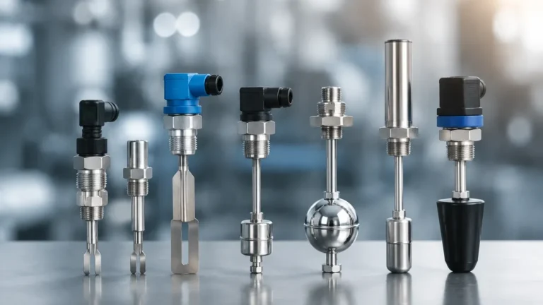
Float switches are the most traditional form of point level detection. They operate on the principle of buoyancy, where a float moves with the liquid level to mechanically actuate a microswitch or move a magnet past a reed switch. The controller in this setup typically monitors a dry contact closure.
Vibrating Tuning Fork Principle
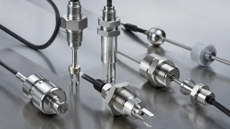
A vibrating level switch uses an electronic circuit to energize a tuning fork at its resonant frequency. When the fork is immersed in a liquid or solid, the frequency changes. The level switch controller detects this frequency shift and toggles the output relay. This method is highly resistant to turbulence, foam, and bubbles.
Conductive Principle
For conductive liquids like water or acids, conductivity probes are often used. A low-voltage AC signal is passed between electrodes. When the liquid touches the probes, the circuit is completed. The controller measures the resistance and triggers when it falls below a specific threshold.
Capacitive Principle
Capacitive switches measure the change in capacitance between a probe and the vessel wall (or a reference electrode). As the medium displaces air, the dielectric constant changes, altering the capacitance. These are effective for both liquids and solids but require calibration based on the material's properties.
The Role of the Level Switch Controller
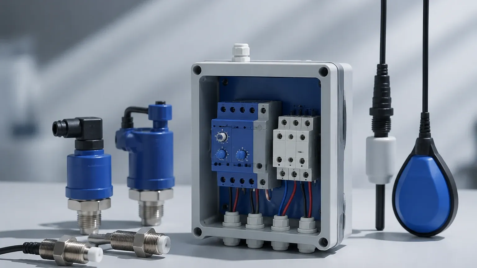
A level switch controller is an electronic device designed to interface with one or more level sensors. Its primary functions include power distribution, signal conditioning, and logic execution.
Signal Processing and Hysteresis
One of the most vital roles of the controller is managing "chatter." In tanks with turbulent surfaces or splashing, a sensor might flicker on and off rapidly. A high-quality level switch controller includes adjustable time delays (typically 0.5 to 30 seconds) and hysteresis logic to ensure the output relay only triggers when a stable level is reached.
Pump Control Logic (Fill vs. Drain)
Controllers are often configured for specific logic cycles:
* Drain Mode (Pump Down): The controller turns a pump on when the high-level switch is triggered and turns it off when the low-level switch is cleared. This is standard for sump and wastewater management.
* Fill Mode (Pump Up): The controller activates a valve or pump when the level drops below the low-level switch and stops it when the high-level switch is reached. This is used for header tanks and process supply vessels.
Multi-Point Monitoring
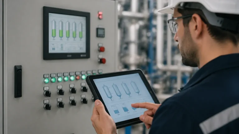
Advanced controllers can handle multiple inputs, allowing for tiered alarm systems. A typical configuration might include:
1. Low-Low Alarm: Dry run protection for pumps.
2. Low Level: Start fill cycle.
3. High Level: Stop fill cycle.
4. High-High Alarm: Overflow prevention and emergency shutdown.
Technical Selection Criteria
Selecting the correct level switch controller requires an evaluation of both the electrical environment and the physical characteristics of the media. The following table provides a comparison of common configurations.
| Feature | Conductive Controller | Ultrasonic/Optical Controller | Tuning Fork/Vibrating Controller |
| :— | :— | :— | :— |
| Best For | Conductive liquids (Water, Acids) | Clean liquids, non-contact needs | Powders, granulates, viscous liquids |
| Media Constraints | Must be conductive (>10 μS/cm) | Affected by heavy foam/steam | Affected by significant buildup |
| Output Type | Relay (SPDT/DPDT) | Relay or Transistor (PNP/NPN) | Relay or Two-wire contactless |
| Mounting | DIN Rail or Wall Mount | Integrated or Remote | Usually Integrated in Sensor Head |
| Maintenance | Low (if probes are non-fouling) | Low (no moving parts) | Moderate (check for coating) |
Power Supply and Input Compatibility
Controllers are typically available in 24V DC or 110V/220V AC versions. It is critical to ensure the controller provides the correct excitation voltage for the sensor. For example, some sensors require a regulated 12V DC loop, while others operate on a 2-wire AC/DC wide-range input.
Enclosure and Environment
If the controller is mounted near the process, it must have an appropriate Ingress Protection (IP) rating. For indoor control cabinets, IP20 (DIN rail) is sufficient. For outdoor or wash-down areas, an IP65 or IP66 rated enclosure is required to protect the electronics from moisture and dust.
Installation and Wiring Considerations
Proper installation is paramount to the reliability of a level switch controller system. Errors in wiring or placement often lead to false triggers or equipment failure.
Wiring Distances and Shielding
For sensors located far from the control room (e.g., more than 50 meters or 164 feet), electromagnetic interference (EMI) can induce noise into the signal lines. Engineers should use shielded twisted-pair cables and ensure the shield is grounded at only one end (usually the controller end) to avoid ground loops.
Fail-Safe Logic
Safety is a primary concern in level control. Controllers should be configured in a "fail-safe" mode.
* High-Level Fail-Safe: The relay is energized when the level is low and de-energizes when the level is high or if power is lost. This ensures that a power failure triggers a high-level alarm, preventing an overflow.
* Low-Level Fail-Safe: The relay is energized when the level is high and de-energizes when the level is low or power is lost, protecting pumps from running dry during a power outage.
Sensor Positioning
Sensors should be installed away from inlet pipes where falling liquid can cause false triggers. If the tank has an agitator, the sensors must be positioned to avoid the vortex or mechanical interference from the blades. In deep sumps, stilling wells (pipes with vent holes) can be used to provide a calm area for the sensor to operate.
Common Risks and Limitations
While level switch controllers are robust, they have inherent limitations compared to continuous measurement systems.
1. Lack of Granularity: A level switch controller only knows if the level is "above" or "below" a point. It cannot tell you if a tank is at 45% or 55% capacity. If precise inventory management is required, a radar or ultrasonic transmitter is more appropriate.
2. Media Buildup: In applications involving sticky resins or wastewater with high solids content, material can build up on the sensor. This may cause a "bridging" effect where the sensor remains triggered even after the liquid level has dropped. Regular inspection and the use of specialized coatings or vibrating sensors can mitigate this.
3. Specific Gravity Changes: For buoyancy-based switches, significant changes in the liquid's density (specific gravity) can affect the trip point. If a process switches between different chemicals, the float may no longer function as intended.
Frequently Asked Questions (FAQ)
Q: Can I use a single level switch controller for two different tanks?
A: Yes, if the controller is a multi-channel unit. However, for safety-critical applications, it is often recommended to have independent controllers to prevent a single point of failure from affecting multiple processes.
Q: What is the difference between a relay output and a transistor output?
A: A relay output is a mechanical switch capable of handling higher currents (e.g., 5A at 250V AC), suitable for direct pump control. A transistor output (PNP/NPN) is electronic, switches much faster, and is typically used to send signals to a PLC (Programmable Logic Controller).
Q: How do I test the controller without filling the tank?
A: Most modern controllers have a "Test" or "Simulate" button. For the sensors, you can manually lift a float, immerse a tuning fork in a bucket of water, or use a jumper wire (for conductive probes) to verify the controller logic.
Q: Is a level switch controller necessary if I have a PLC?
A: While a PLC can perform the logic, a dedicated level switch controller provides an extra layer of redundancy. In many industrial safety standards, a hardware-based level controller is required for high-high emergency shutdown independent of the primary PLC software.
Conclusion
The level switch controller remains a cornerstone of industrial process control. By selecting the appropriate sensing technology—whether it be the simplicity of a float or the precision of a vibrating fork—and pairing it with a correctly configured controller, facilities can ensure reliable protection against overflows and dry-run conditions. When designing your system, always prioritize fail-safe configurations and consider the physical properties of the medium to ensure long-term, maintenance-free operation.