Level Switch Wiring
Level Switch Wiring
In industrial automation and process control, the reliability of a system often depends on the integrity of its point-level detection. Level switch wiring is a critical phase of installation that bridges the gap between physical sensing and electronic control. Whether managing a simple water tank or a complex chemical reactor, understanding the electrical interface of Level Switches ensures operational safety, prevents equipment damage from overfills, and avoids the costly downtime associated with dry-run conditions.
This guide provides a comprehensive technical overview of level switch wiring, covering measurement principles, contact configurations, wiring diagrams for various technologies, and essential installation practices for engineering professionals.
Measurement Principles and Electrical Output
Before addressing the specifics of level switch wiring, it is essential to understand how these devices function. A level switch is a binary sensor designed to respond to the presence or absence of a medium at a specific height. Unlike continuous level transmitters that provide a 4-20mA or 0-10V signal representing the entire range, a level switch changes its electrical state only when the set point is reached.
Mechanical vs. Electronic Switching
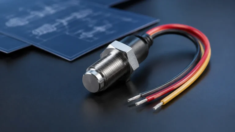
1. Mechanical Switches (e.g., Float Switches): These utilize a physical movement—such as a rising float—to mechanically actuate a microswitch or move a magnet to trigger a reed switch. These are typically "dry contact" devices, meaning they do not require external power to operate the sensing mechanism itself.
2. Electronic Switches (e.g., Tuning Fork, Capacitance, Ultrasonic): These devices use electronic circuits to detect changes in frequency, capacitance, or sound waves. They require an external power supply (typically 24V DC or 110/230V AC) to power the internal electronics and provide an output signal, which may be a relay, a transistor (PNP/NPN), or a contactless electronic switch.
Fundamental Wiring Concepts
Successful level switch wiring requires familiarity with standard terminal designations and contact behaviors. Most industrial level switches utilize one of the following configurations:
Contact Types: NO vs. NC
* Normally Open (NO): The circuit is open (no current flows) when the switch is in its "rest" or non-actuated state. When the level reaches the switch, the contact closes.
* Normally Closed (NC): The circuit is closed when the switch is at rest. When the level reaches the switch, the contact opens, breaking the circuit.
Relay Configurations: SPDT and DPDT
* SPDT (Single Pole Double Throw): This is the most common configuration in level switch wiring. It consists of three terminals: Common (COM), Normally Open (NO), and Normally Closed (NC). This allows the user to choose the logic required for the application.
* DPDT (Double Pole Double Throw): This configuration provides two independent sets of SPDT contacts. This is useful for simultaneously triggering a local alarm and sending a signal to a PLC (Programmable Logic Controller).
Level Switch Wiring by Technology Type
Different sensing technologies dictate specific wiring requirements. Below are the most common industrial setups.
1. Float Level Switch Wiring
Magnetic float switches often use a reed switch mechanism. Because they are passive, they are frequently wired in series with the load or a control relay.
* 2-Wire Configuration: Simple on/off logic. One wire connects to the power source, and the other connects to the load.
* Caution: Reed switches have low current ratings (often <1A). Wiring a high-power pump directly to a reed-based float switch will cause the contacts to weld shut. Always use an intermediate relay for inductive loads.
2. Vibrating (Tuning Fork) Level Switch Wiring
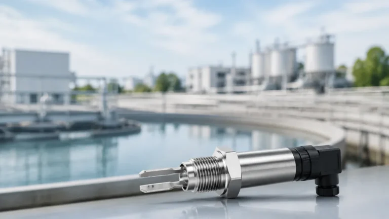
Vibrating switches are active devices. They typically feature a 3-wire or 4-wire setup.
* DC 3-Wire (PNP/NPN):
* Brown: Positive (+VDC)
* Blue: Negative (0V)
* Black: Output signal. In a PNP setup, the output provides +VDC when active; in an NPN setup, it provides 0V.
* AC/DC Relay Output: These often have 5 terminals: two for power supply and three for the SPDT relay contacts (COM, NO, NC).
3. Capacitance Level Switch Wiring
Capacitance switches detect the change in dielectric constant. Their wiring is similar to tuning forks but often includes an additional terminal for a "shield" or "guard" to prevent false triggering from material buildup on the probe.
4. Conductivity Level Switch Wiring
Used for conductive liquids, these require a controller. The wiring involves connecting the probe electrodes to the controller terminals. The controller then provides the relay output for the process equipment.
Wiring Configurations: 2-Wire, 3-Wire, and 4-Wire
| Configuration | Description | Common Application |
| :— | :— | :— |
| 2-Wire (Passive) | Simple mechanical contact; no external power for the sensor. | Basic tank high/low alarms using float switches. |
| 2-Wire (Active) | Loop-powered; the device draws a small leakage current to power itself. | Modern electronic switches integrated into 4-20mA loops. |
| 3-Wire (DC) | Requires V+, GND, and a Transistor output (PNP/NPN). | High-speed switching in factory automation and OEM machinery. |
| 4-Wire / 5-Wire | Separate power supply pairs and isolated relay contact pairs. | Industrial process control where the load is on a different voltage circuit. |
Practical Selection Table for Level Switch Wiring
When selecting a device, consider the electrical environment and the control system interface.
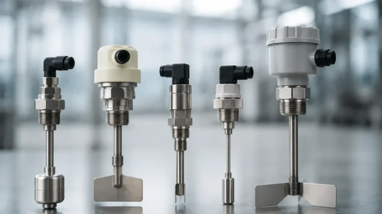
| Feature | Float Switch | Tuning Fork | Capacitance | Conductivity |
| :— | :— | :— | :— | :— |
| Power Required | No | Yes | Yes | Yes (Controller) |
| Output Type | Dry Contact | Relay / PNP / NPN | Relay / PNP / NPN | Relay |
| Wiring Complexity | Low | Moderate | Moderate | Moderate |
| Voltage Drop | Negligible | ~1-2V (Electronic) | ~1-2V (Electronic) | N/A |
| Max Distance | Up to 100m+ | Limited by V-drop | Limited by V-drop | Limited by Resistance |
Installation Considerations and Best Practices
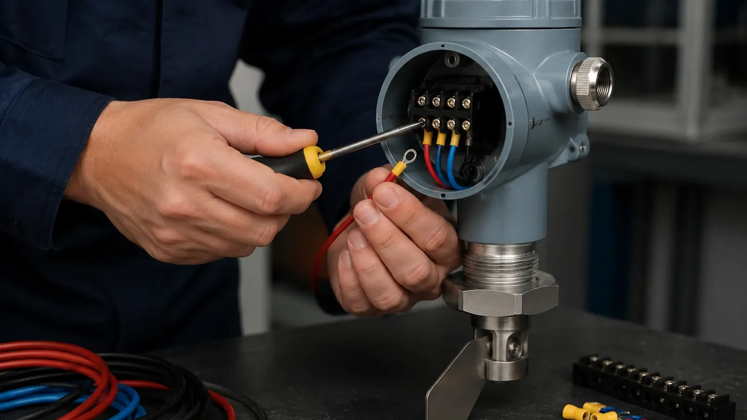
Proper level switch wiring extends beyond simply connecting terminals; it involves protecting the signal integrity and ensuring physical durability.
1. Cable Selection and Shielding
For electronic level switches, use shielded twisted pair (STP) cables to prevent electromagnetic interference (EMI) from VFDs (Variable Frequency Drives) or high-voltage motors. The shield should be grounded at only one end (usually the control cabinet) to avoid ground loops.
2. Conduit and Sealing
In applications involving liquids, moisture ingress is a primary cause of wiring failure.
* Drip Loops: Always form a "U" shape with the cable before it enters the cable gland. This ensures that condensation or rainwater drips off the cable rather than running into the housing.
* Sealing: Use appropriate cable glands (IP66/IP67/IP68) and ensure the housing cover is tightened to the manufacturer's torque specifications.
3. Voltage Drop Calculations
For long cable runs (exceeding 50 meters) with DC-powered switches, calculate the voltage drop. If the voltage at the sensor terminals falls below the minimum operating threshold (e.g., <18V DC for a 24V device), the switch may behave erratically or fail to trigger.
4. Hazardous Area Wiring
If the level switch is installed in a Zone 0, 1, or 2 hazardous area, specific wiring methods are mandatory:
* Intrinsically Safe (IS): Requires the use of a Zener barrier or galvanic isolator in the safe area to limit the energy sent to the switch.
* Flameproof/Explosion-Proof: Requires the use of armored cable and certified explosion-proof conduits and glands.
Limitations and Common Risks
* Contact Overloading: Wiring a motor or high-wattage heater directly to a level switch contact is a frequent error. Even if the switch is rated for 5A, the inrush current of a motor can be 5-10 times the running current, leading to immediate contact failure.
* Inductive Kickback: When switching DC inductive loads (like solenoid valves), a flyback diode should be installed across the load to protect the switch contacts from high-voltage spikes during de-energization.
* Incorrect Logic: Reversing NO and NC wiring can lead to dangerous overflows. Always verify the "fail-safe" state. For example, a high-level alarm should typically be wired so that the circuit opens upon alarm or loss of power (Normally Closed logic for fail-safe).
Frequently Asked Questions (FAQs)
Q: Can I use a single level switch to start and stop a pump?
A: A single point level switch cannot provide the "hysteresis" needed to prevent a pump from rapidly cycling (chattering). You must either use two switches (one for start, one for stop) with a latching relay circuit or a single switch with a built-in differential or a PLC program.
Q: What is the difference between PNP and NPN wiring in level switches?
A: This refers to how the load is connected. In PNP wiring, the switch connects the load to the positive voltage (Sourcing). In NPN wiring, the switch connects the load to the negative/ground (Sinking). Your PLC input card type determines which one you need.
Q: How do I test the wiring without filling the tank?
A: Most electronic Level Switches have a local LED indicator. For mechanical switches, you can manually lift the float or use a multimeter in continuity mode to verify the state change at the terminal block.
Q: Why is my switch triggering when the tank is empty?
A: This is often caused by moisture in the junction box (shorting the terminals), improper grounding causing EMI, or material buildup on the probe (for capacitance/tuning fork types) that mimics the presence of the medium.
Conclusion
Level switch wiring is the final, critical step in ensuring an automated level control system operates as designed. By selecting the correct contact configuration, adhering to shielding and sealing standards, and respecting the electrical limits of the device, engineers can ensure long-term reliability. Always consult the specific wiring diagram provided by the manufacturer for your model, as terminal numbering can vary between brands. For complex applications, integrating these switches into a robust PLC environment with proper fail-safe logic remains the industry standard for process safety.