Level Switch PDF
Level Switch PDF
In industrial process control, point level detection serves as a critical safeguard for inventory management, pump protection, and overfill prevention. Selecting the correct instrument requires a deep understanding of physical measurement principles, fluid dynamics, and environmental constraints. This technical guide serves as a comprehensive reference—equivalent to a professional level switch pdf datasheet—to assist engineers and procurement specialists in identifying the optimal technology for their specific application.
Understanding Point Level Measurement Principles
Unlike continuous level transmitters that provide a constant 4-20mA or digital signal representing the exact level, Level Switches are designed to detect the presence or absence of material at a specific height. When the media reaches the sensor's position, the device triggers a state change in an electrical contact (typically a relay or transistor).
1. Vibrating Fork (Tuning Fork) Principle
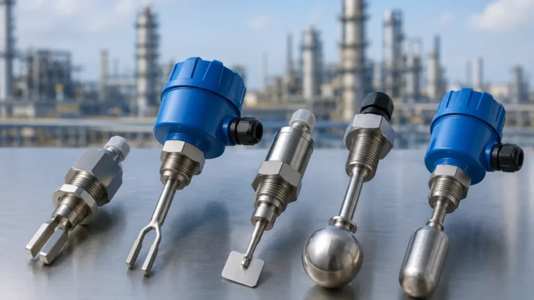
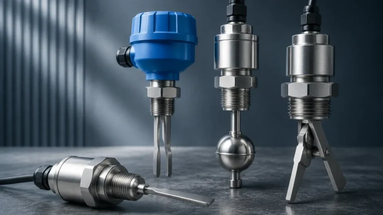
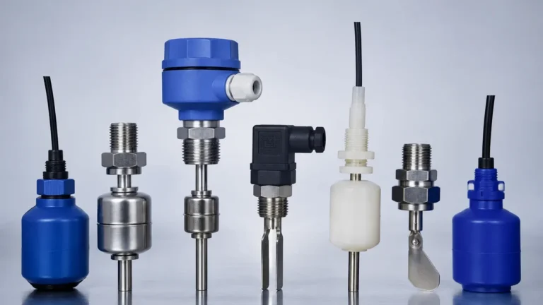
The vibrating fork sensor utilizes piezoelectric crystals to excite a metal fork at its natural resonant frequency (typically around 1200 Hz). When the fork is immersed in a liquid or solid, the frequency shifts or the amplitude drops. The internal electronics detect this change and switch the output. This technology is highly versatile because it is largely unaffected by flow, bubbles, or changes in the dielectric constant of the media.
2. Float and Magnetic Principles
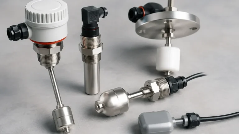
Float switches rely on buoyancy. A float containing a permanent magnet moves with the liquid level. As the float passes a stationary reed switch located inside a sealed stem, the magnetic field causes the reed contacts to open or close. For more complex setups, magnetic level switches can be mounted externally to a bypass chamber, allowing for maintenance without breaking the process seal.
3. Capacitance Principle
Capacitive level switches treat the sensor probe and the tank wall as two plates of a capacitor. The air or vapor space acts as one dielectric, and the process media acts as another. As the media covers the probe, the capacitance increases due to the higher dielectric constant ($ε$) of the material compared to air. This change is converted into a switching signal. This method is effective for both liquids and bulk solids but may require calibration for different materials.
4. Rotary Paddle Principle
Specifically designed for bulk solids and powders, the rotary paddle switch uses a low-speed motor to turn a paddle. When the material rises to the level of the paddle, it restricts the rotation. The resulting torque causes the motor to shift on its mounting, triggering a microswitch and cutting power to the motor to prevent burnout. This is a robust solution for silos containing grain, plastic pellets, or cement.
5. Hydrostatic Pressure Switches
While often used for continuous measurement, hydrostatic sensors can be configured as switches. They measure the pressure exerted by the liquid column above the sensor ($P = ρgh$). Once a set pressure threshold is reached, the switch activates. These are frequently used in water treatment and deep-well applications.
Practical Selection Criteria
Choosing the right instrument involves more than just identifying the media. Engineers must consult a technical level switch pdf to verify compatibility with the following parameters:
Media Characteristics
* State: Is it a liquid, slurry, or bulk solid?
* Viscosity: High-viscosity liquids (e.g., heavy oils) can cause "clinging" on vibrating forks or capacitance probes, leading to false positives.
* Corrosivity: Ensure the wetted parts (316L stainless steel, PTFE, or PP) are compatible with the chemical composition.
* Conductivity: Conductivity switches require the media to be electrically conductive to complete a circuit between two electrodes.
Process Conditions
* Temperature: Standard industrial switches typically handle -40°C to 150°C. High-temperature variants with cooling fins are required for steam or furnace applications.
* Pressure: Standard threads (G1/2", 1" NPT) are usually rated for 10 bar (1 MPa) to 40 bar (4 MPa). High-pressure applications may require specialized flange mountings.
* Turbulence and Foam: Foam can trigger some ultrasonic or capacitive switches prematurely. Vibrating forks are generally the most resistant to foam interference.
Comparison Table for Level Switch Technologies
| Technology | Best For | Limitations | Typical Industry |
| :— | :— | :— | :— |
| Vibrating Fork | Liquids, light powders | Not for very high viscosity | Food & Beverage, Chemical |
| Float Switch | Clean liquids, water | Moving parts can jam; no solids | Water Treatment, HVAC |
| Capacitance | Corrosive liquids, solids | Requires calibration; coating issues | Chemical, Mining |
| Rotary Paddle | Bulk solids, grains | Mechanical wear; solids only | Agriculture, Construction |
| Conductivity | Conductive liquids | Not for oils or non-conductive fluids | Wastewater, Sumps |
| Optical | Clear liquids, leak detection | Sensitive to coating/scaling | Laboratory, Pharmaceutical |
Installation and Engineering Considerations
Proper installation is vital to the longevity and accuracy of Level Switches. Even the highest quality sensor will fail if placed incorrectly within a vessel.
1. Mounting Orientation
Most switches can be mounted horizontally (through the side wall) or vertically (from the top). For horizontal mounting, ensure the probe is angled slightly downward to allow liquid to drain off, preventing "buildup" errors. For vibrating forks, the tines should be oriented so that the liquid can flow through them rather than being trapped against the flat surface.
2. Avoiding the Fill Stream
Never install a level switch directly in the path of the incoming material flow. The force of the falling media can cause mechanical damage or trigger false alarms. If the sensor must be near an inlet, a protective baffle or shield should be installed.
3. Electrical Wiring and Fail-Safe Modes
When reviewing a level switch pdf, pay close attention to the "Fail-Safe" settings.
* High Level Fail-Safe (FSH): The relay is energized when the level is low and de-energizes when the level is high or if power is lost. This prevents overfills during a power failure.
* Low Level Fail-Safe (FSL): The relay is energized when the level is high and de-energizes when the level is low or power is lost. This protects pumps from running dry.
4. Dead Zones and Hysteresis
Every switch has a "dead zone" where it cannot detect level, and a "hysteresis" range (the difference between the switch-on and switch-off points). Hysteresis is necessary to prevent "chattering" of the relay if the liquid surface is turbulent or wavy.

Limitations and Common Risks
While level switches are robust, they are not universal solutions. Engineers should be aware of the following risks:
* Material Buildup: In applications involving wastewater or lime slurry, material can cake onto the sensor. Capacitance switches with "active shield" technology or vibrating forks with specialized coatings are often required to mitigate this.
* Vibration Interference: In heavy industrial environments, external machine vibration can occasionally interfere with the resonant frequency of a vibrating fork. In such cases, a capacitive or hydrostatic sensor may be more reliable.
* Dielectric Changes: If a capacitance switch is calibrated for an oil ($ε ≈ 2$) but the tank is later used for water ($ε ≈ 80$), the switch point will change significantly.
Frequently Asked Questions (FAQ)
Q: Can a level switch be used for continuous monitoring?
A: No. A level switch only provides a binary (on/off) signal. For continuous monitoring, a radar or ultrasonic level meter is required.
Q: What is the difference between SPDT and DPDT contacts?
A: SPDT (Single Pole Double Throw) has one set of contacts to control one circuit. DPDT (Double Pole Double Throw) has two sets, allowing you to control two independent circuits (e.g., one for a pump and one for a remote alarm) with a single switch.
Q: How do I test a level switch without filling the tank?
A: Many modern vibrating forks and electronic switches include a "test" magnet or button on the housing that simulates a high-level condition to verify the loop and alarm logic.
Q: Are level switches suitable for explosive environments?
A: Yes, but you must specify an intrinsically safe (Ex i) or explosion-proof (Ex d) version. These will be clearly marked in the technical level switch pdf documentation with the appropriate ATEX, IECEx, or UL certifications.
Conclusion
Selecting the right point level detection technology is a balance of physical properties, process demands, and budget. By consulting the technical specifications found in a level switch pdf and understanding the underlying measurement principles—whether it be the frequency shift of a vibrating fork or the buoyancy of a magnetic float—engineers can ensure long-term reliability and safety in their operations. For detailed product specifications and application-specific advice, it is recommended to review the latest industrial Level Switches documentation to match the instrument to the unique requirements of the facility.