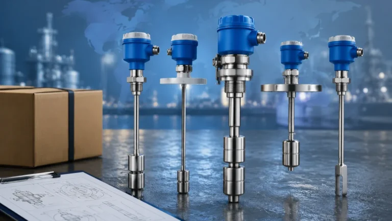
Level Switch with Controller
Level Switch with Controller
In industrial process automation, point-level detection serves as a critical safety and operational layer. While continuous level measurement provides a real-time percentage of tank volume, point-level devices—commonly known as Level Switches—are designed to trigger specific actions when a substance reaches a predetermined height. To translate these physical detections into actionable logic, such as starting a pump or sounding an alarm, a level switch with controller configuration is often employed. This integrated approach ensures that the raw signal from the sensor is conditioned, filtered, and used to manage electrical loads safely.
Measurement Principles for Point Level Detection
Before selecting a level switch with controller, it is essential to understand the underlying physics of the sensors themselves. Different media (liquids, slurries, or solids) interact differently with sensor technologies.
Tuning Fork (Vibrating) Principle
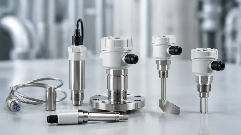
This technology utilizes a fork-shaped sensing element that vibrates at its natural resonant frequency in the air. When the media covers the tines, the frequency shifts or the vibration is damped. An internal electronic circuit detects this change and converts it into an output signal. Tuning fork switches are highly reliable for most liquids and free-flowing powders because they are largely unaffected by flow, turbulence, bubbles, or foam.
Ultrasonic Point Level Principle
Ultrasonic switches use a pair of crystals: one to transmit high-frequency sound and one to receive it. When the gap between the crystals is filled with liquid, the sound waves travel across; when the gap is empty (filled with air or gas), the waves are attenuated. This is a non-contact-ish method (the gap must be submerged) that is excellent for clean liquids but can struggle with high-viscosity fluids that coat the sensor gap.
Capacitive Principle
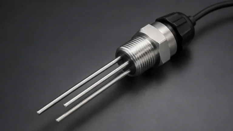
Capacitive sensors measure the change in capacitance between a probe and the tank wall (or a reference probe). As the level rises, the air surrounding the probe is replaced by the process media, which has a different dielectric constant. This change in capacitance triggers the switch. These are versatile but require calibration to the specific dielectric properties of the media.
Float and Displacement Principle
One of the oldest technologies, float switches rely on buoyancy. A magnetic float moves with the liquid level, actuating a reed switch inside a stationary stem. While simple and cost-effective, they are mechanical in nature and can fail if the media contains debris that jams the moving parts.
The Role of the Controller in Level Systems
A level switch with controller system separates the sensing function from the logic and power handling functions. While many modern switches include basic internal relays, a dedicated controller provides several engineering advantages:
1. Signal Conditioning and Power Supply: The controller often provides the stabilized DC power required by the sensor, simplifying the field wiring.
2. Logic and Hysteresis: A controller allows for "pump-up" or "pump-down" logic. For example, a controller can be programmed to start a pump when the level reaches a low switch and stop it only when it reaches a high switch. This prevents "chattering," where a single switch rapidly toggles on and off due to surface turbulence.
3. Time Delays: To avoid false triggers from splashing or momentary surges, controllers can implement adjustable time delays (typically 0.5 to 30 seconds).
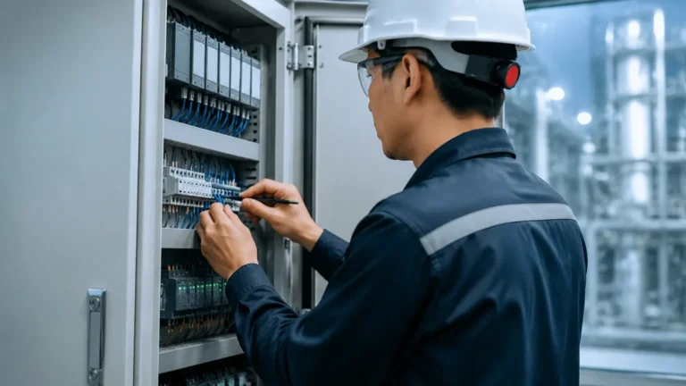
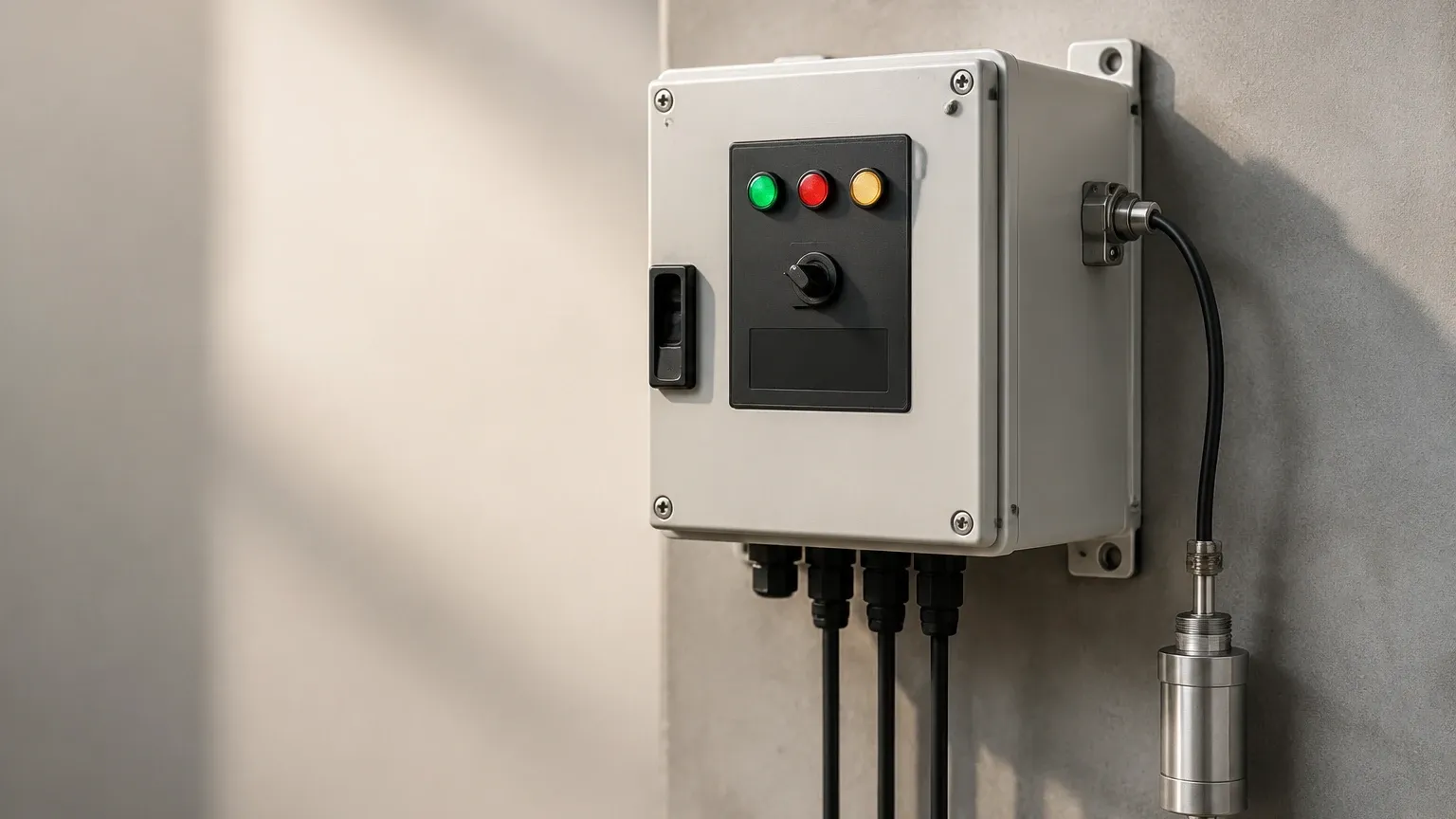
4. Remote Monitoring: Controllers are usually mounted in a control room or a DIN-rail cabinet, providing visual LED indicators for operators without requiring them to check the tank top.
Selection Criteria for Industrial Applications
Choosing the right level switch with controller requires a detailed analysis of the process environment. Engineers should evaluate the following parameters:
* Media Characteristics: Is the material liquid, solid, or slurry? What is its density and viscosity? For example, a tuning fork switch is ideal for light powders, while a heavy-duty float might be better for water storage.
* Process Conditions: Operating temperatures can range from -40°C to over 250°C in specialized applications. Pressure ratings must also match the vessel's design, often requiring 1.6 MPa (16 bar) or higher.
* Output Requirements: Does the system need a simple SPDT relay, a DPDT relay for redundant signaling, or a transistor (PNP/NPN) output for PLC integration?
* Housing and Protection: For outdoor or wash-down environments, IP65 to IP68 ratings are standard. In hazardous areas, explosion-proof (Ex d) or intrinsically safe (Ex i) certifications are mandatory.
Technical Selection Table
The following table provides a general guideline for matching technology with common industrial requirements.
| Technology | Media Type | Temp. Range (Typical) | Max Pressure | Best For |
| :— | :— | :— | :— | :— |
| Tuning Fork | Liquids / Solids | -40 to 150°C | 4.0 MPa | Overfill protection, pump dry-run |
| Ultrasonic | Clean Liquids | -20 to 80°C | 0.6 MPa | Chemical storage, non-contact |
| Capacitive | Liquids / Slurries | -40 to 200°C | 2.5 MPa | High-temperature, coating media |
| Float | Water / Oil | -10 to 120°C | 1.0 MPa | Simple sump control, low cost |
| Optical | Clear Liquids | -20 to 100°C | 1.0 MPa | Leak detection, small tanks |
Installation and Configuration Guidelines
Proper installation is as critical as sensor selection. Even the most advanced level switch with controller will fail if positioned incorrectly.
Mounting Position
Switches can be mounted horizontally (through the side of the tank) or vertically (from the top). For side mounting, ensure the sensor is not placed directly under a fill pipe, as the falling material will cause false high-level readings. If top-mounting a long probe, ensure it is clear of internal agitators or baffles.
Wiring and Grounding
Industrial environments are prone to electromagnetic interference (EMI). Use shielded cables for the connection between the switch and the controller. Ensure the controller is properly grounded to the common plant ground to prevent signal drift in capacitive systems.
Calibration and Testing
While tuning fork and ultrasonic switches are often "plug-and-play," capacitive and displacement switches require calibration.
1. Dry Calibration: Set the zero point when the tank is empty.
2. Wet Calibration: Adjust the sensitivity when the media covers the probe to ensure a decisive switch action.
3. Simulation: Most controllers feature a "test" button or a manual override to verify that the connected pumps or valves respond correctly to a switch trigger.
Common Limitations and Troubleshooting
Understanding the limitations of a level switch with controller helps in preventative maintenance:
* Material Buildup: In sticky or viscous applications, material can accumulate on the sensor. While some tuning forks and capacitive probes have "active shield" technology to ignore buildup, excessive coating will eventually cause a permanent "high" signal.
* Turbulence and Foam: Ultrasonic and optical sensors may struggle with heavy foam, as the signal is absorbed rather than reflected. In these cases, a tuning fork or a mechanical float is more reliable.
* Ambient Temperature: Controllers mounted in unventilated outdoor cabinets can overheat in summer months, leading to logic errors or shortened component life. Always check the ambient temperature rating of the controller unit (usually up to 55°C or 60°C).
Frequently Asked Questions (FAQs)
Q: Can a single level switch with controller manage both high and low levels?
A: A single point-level switch can only detect one level. To manage both high and low levels (e.g., for automatic tank filling), you typically need two switches connected to a single dual-channel controller that handles the start/stop logic.
Q: What is the difference between a relay output and a transistor output?
A: A relay output is a mechanical switch capable of handling higher currents (e.g., 5A at 250VAC), suitable for direct control of small motors or solenoid valves. A transistor output (PNP/NPN) is electronic, faster, and has a longer lifespan, but it is low-power and intended for signaling a PLC or DCS.
Q: How far can the controller be located from the sensor?
A: This depends on the signal type. For standard relay-based switches, distances of up to 300 meters (approx. 1000 feet) are possible with high-quality copper wiring. For high-frequency capacitive signals, the distance is much shorter unless a signal transmitter is used to convert the raw data into a 4-20mA or digital signal.
Q: Are these systems compatible with corrosive chemicals?
A: Yes, but material selection is vital. For corrosive acids, sensors should be constructed from 316L Stainless Steel, PTFE, or PVDF. The controller itself should be housed in a protected area or a NEMA 4X / IP66 rated enclosure.
Conclusion
Implementing a level switch with controller is a foundational step in securing industrial processes against overflows and dry-run conditions. By understanding the specific measurement principles—whether vibrating, ultrasonic, or capacitive—and pairing them with a robust controller, engineers can create a reliable automated system. When selecting your components, always prioritize the physical properties of your media and the environmental constraints of your facility to ensure long-term accuracy and safety. For more specialized configurations, reviewing various Level Switches options will help determine the most cost-effective and technically sound solution for your specific application.