Ultrasonic Level Gauge Hs Code
Understanding the Ultrasonic Level Gauge HS Code and Measurement Principles
In the landscape of industrial automation and process control, the accurate measurement of liquid levels is fundamental to operational safety and efficiency. Among the various technologies available, ultrasonic level meters have emerged as a preferred solution for non-contact measurement in water treatment, chemical processing, and oil and gas industries. However, for procurement professionals, engineers, and global distributors, technical specifications are only one part of the equation. Understanding the regulatory and logistical framework—specifically the ultrasonic level gauge hs code—is essential for seamless international trade and compliance.
This guide explores the technical foundations of ultrasonic measurement, provides a detailed breakdown of Harmonized System (HS) classifications, and offers practical advice for selecting and installing these instruments in diverse industrial environments.
Measurement Principles of Ultrasonic Level Meters
Before diving into the logistics of the ultrasonic level gauge hs code, it is vital to understand how these devices function. Ultrasonic Level Meters operate on the "Time-of-Flight" (ToF) principle.
The Transducer and Pulse Emission
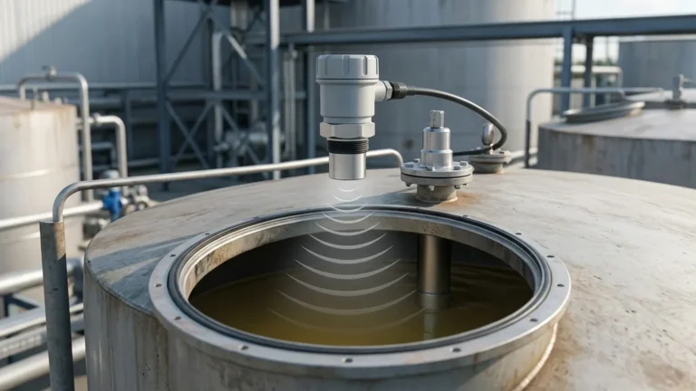
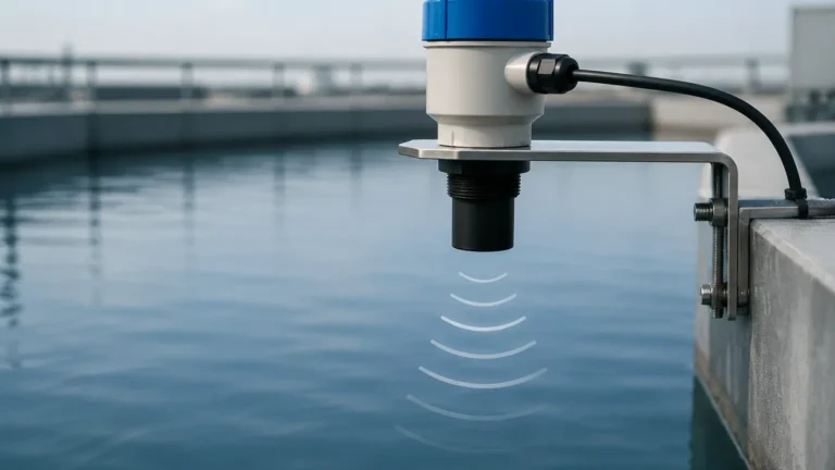
The core of the instrument is the transducer, which typically contains a piezoelectric crystal. When energized, this crystal vibrates at a specific frequency, emitting a burst of ultrasonic sound waves. These waves travel through the air or gas space above the medium at the speed of sound.
Reflection and Detection
When the sound waves reach the surface of the liquid or solid being measured, they are reflected back toward the sensor. The transducer then acts as a receiver, converting the returning acoustic energy back into an electrical signal.
Calculation of Distance
The internal microprocessor calculates the time interval between the emission of the pulse and the reception of the echo. The distance ($D$) from the sensor to the material surface is determined using the formula:
$$D = \frac{c \times t}{2}$$
Where:
* c is the speed of sound in the medium (approximately 343 m/s in air at 20°C).
* t is the total transit time.
The device then subtracts this distance from the total tank height (the "zero point") to determine the actual level of the material. Modern instruments like those from Welk incorporate advanced algorithms to filter out "false echoes" caused by internal tank structures like ladders or agitators.
Decoding the Ultrasonic Level Gauge HS Code
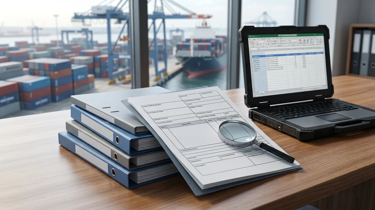
For international shipping and customs clearance, every product must be classified under the Harmonized System. The ultrasonic level gauge hs code is critical because it determines the duty rates, taxes, and regulatory requirements applied to the shipment.
Primary Classification
Most ultrasonic level measurement instruments fall under Chapter 90 of the HS nomenclature, which covers "Optical, photographic, cinematographic, measuring, checking, precision, medical or surgical instruments and apparatus."
Specifically, the most common heading is 9026:
* *Instruments and apparatus for measuring or checking the flow, level, pressure or other variables of liquids or gases (for example, flow meters, level gauges, manometers, heat meters).*
Subheading Breakdown
Within heading 9026, the classification becomes more specific:
* 9026.10: For measuring or checking the flow or level of liquids.
* 9026.10.11 / 9026.10.19: These sub-codes often distinguish between electronic and non-electronic instruments. As ultrasonic meters are electronic, they typically fall under the electronic sub-classification.
| Region | Typical HS Code Structure | Description |
| :— | :— | :— |
| International (Harmonized) | 9026.10 | Instruments for measuring/checking liquid level/flow. |
| United States (HTS) | 9026.10.20 | Electrical instruments for measuring or checking liquid levels. |
| European Union (CN) | 9026.10.21 | Electronic flow meters or level gauges. |
| China (HS) | 9026.10.00 | Instruments and apparatus for measuring or checking the level of liquids. |
Note: While 9026 is the standard, if the ultrasonic meter is part of a complex control system, it may occasionally be classified under 9032 (Automatic regulating or controlling instruments). It is always advisable to consult with a customs broker to confirm the exact ultrasonic level gauge hs code for your specific region and application.
Key Selection Criteria for Industrial Applications
Choosing the right ultrasonic meter requires a balance between technical requirements and budget constraints. Engineers should evaluate the following factors:
1. Measurement Range
Ultrasonic sensors have a maximum range (often up to 15 meters or 30 meters for high-power models) and a "dead zone" (or blocking distance). The dead zone is the area immediately below the sensor (typically 0.25m to 0.6m) where measurement is impossible. Ensure the sensor is mounted high enough so the liquid never enters this zone.
2. Process Environment
* Temperature: The speed of sound varies with temperature. Ensure the meter has integrated temperature compensation.
* Pressure: Ultrasonic waves do not travel well in high-pressure environments or vacuums. They are generally limited to near-atmospheric pressures (typically -0.5 to 3 bar).
* Chemical Compatibility: The transducer face (wetted part) must be resistant to the vapors in the tank. Materials like PVDF or PTFE are common for corrosive environments.
3. Output and Communication
Standard industrial outputs include 4-20mA (analog) and RS485 (Modbus). For modern IoT integration, some models support HART or wireless protocols.
Selection Comparison Table
| Feature | Compact/Integrated Type | Split/Remote Type |
| :— | :— | :— |
| Best For | Simple tanks, outdoor sumps | Hazardous areas, high-mounted tanks |
| Installation | Single unit, easy wiring | Sensor and controller are separate |
| Display | On the sensor head | On the remote controller (eye-level) |
| Cable Length | Limited | Up to 50m – 100m between sensor/host |
| Typical Range | 2m to 15m | 5m to 30m |
Installation Considerations and Best Practices
Proper installation is the most significant factor in the reliability of an ultrasonic level meter. Even the highest quality instrument will fail if the acoustic path is compromised.
Placement and Orientation
* Perpendicularity: The transducer face must be perfectly parallel to the liquid surface. A tilt of even a few degrees can cause the reflected signal to miss the receiver.
* Wall Distance: Avoid mounting the sensor too close to the tank wall. The beam angle (typically 5° to 12°) widens as it travels. If the beam hits the wall, it creates a false echo. A general rule is to maintain a distance from the wall equal to at least 1/6th of the tank height.
* Inflow Avoidance: Never install the sensor directly above the tank's fill inlet. The turbulence and falling liquid will scatter the ultrasonic signal.
Managing Obstructions
Internal structures like heating coils, ladders, or support beams can reflect the signal. While many Welk meters feature "false echo suppression" software, it is best to provide a clear "line of sight" for the acoustic beam.
Limitations and Practical Challenges
While versatile, ultrasonic technology is not a universal solution. Understanding its limitations prevents costly misapplications.
1. Foam and Turbulence: Heavy surface foam absorbs ultrasonic energy rather than reflecting it. If foam is present, a radar level meter or a stilling well may be required.
2. Vapor and Dust: Dense steam, solvent vapors, or heavy dust can attenuate the sound signal, leading to "lost echo" errors.
3. Vacuum: Sound waves require a medium (air/gas) to travel. Ultrasonic meters cannot function in a vacuum.
4. Temperature Gradients: If there is a significant temperature difference between the sensor and the liquid surface, the speed of sound calculation may become inaccurate, despite internal compensation.
Frequently Asked Questions (FAQ)
What is the most common HS code for an ultrasonic level transmitter?
Globally, the most common code is 9026.10. Depending on the country, the suffix may vary (e.g., 9026.10.00 in China or 9026.10.20 in the US).
Why does the dead zone matter?
If the liquid level rises into the dead zone, the sensor cannot process the echo in time, leading to erratic readings or a "full tank" error. Always account for the maximum possible liquid level during installation.
Can ultrasonic meters measure solids?
Yes, but with caveats. Solids (like grain or plastic pellets) often have an uneven surface that scatters the signal. A higher-power transducer and careful positioning are usually necessary for solid level measurement.
How do I maintain an ultrasonic level gauge?
Because they are non-contact, maintenance is minimal. Periodically check the transducer face for condensation or buildup, especially in humid or dusty environments. Ensure the mounting remains secure and perpendicular.
Conclusion
Specifying the correct Ultrasonic Level Meters involves more than just selecting a range and output. By understanding the underlying physics of Time-of-Flight measurement and ensuring compliance with the correct ultrasonic level gauge hs code, industrial operators can ensure both technical success and smooth logistical operations.
For engineers designing new systems, prioritizing a clear acoustic path and accounting for environmental factors like foam and pressure will lead to a robust, low-maintenance level control solution. Whether you are managing water treatment facilities or complex chemical storage, Welk provides the expertise and instrumentation to ensure accuracy in every drop.