Level Sensor Gauge
Level Sensor Gauge
In industrial process control, the term "level sensor gauge" encompasses a broad category of instruments designed to measure the height of liquids, slurries, or granular solids within a vessel. Accurate level measurement is fundamental to operational safety, inventory management, and process efficiency across industries ranging from water treatment and chemical processing to oil and gas production.
Choosing the correct level sensor gauge requires a deep understanding of the physical principles governing different measurement technologies. While some applications require continuous monitoring of the fluid level, others may only require point level detection to prevent overfills or dry-running of pumps. This guide examines the primary technologies used in modern industrial level measurement, their operating principles, and the criteria for selecting the most appropriate instrument for specific process conditions.
Fundamental Measurement Principles
Level measurement technologies are generally divided into two categories: contact and non-contact. Contact sensors physically touch the medium being measured, while non-contact sensors use wave-based technologies to determine the distance to the surface.
Radar Level Measurement
Radar level gauges utilize electromagnetic waves, typically in the microwave spectrum. There are two primary types: non-contact pulse radar and Guided Wave Radar (GWR).
* Non-Contact Radar: These instruments emit a microwave signal toward the product surface. The signal reflects off the surface and returns to the sensor. The time-of-flight (ToF) between emission and reception is used to calculate the distance. Modern high-frequency radar (e.g., 80 GHz) offers narrow beam angles, which minimizes interference from tank internals like agitators or ladders.
* Guided Wave Radar (GWR): GWR uses a physical probe (rod or cable) to guide the microwave pulse to the surface. This technology is highly effective for low-dielectric liquids and applications with heavy foam, steam, or turbulence, as the probe concentrates the signal energy.
Ultrasonic Level Measurement
Ultrasonic sensors emit high-frequency sound pulses (typically 20 kHz to 200 kHz). Similar to radar, the sensor measures the time it takes for the echo to return from the surface. Because sound speed is influenced by air temperature, these sensors usually include an integrated temperature sensor to compensate for variations in the vapor space. They are cost-effective for water and wastewater applications but are less suitable for vacuum environments or high-pressure tanks where sound propagation is inconsistent.
Hydrostatic Level Measurement
Hydrostatic pressure sensors measure the weight of the liquid column above the sensor diaphragm. The relationship is defined by the formula: $P = \rho \cdot g \cdot h$, where $P$ is pressure, $\rho$ is the density of the liquid, $g$ is gravity, and $h$ is the height of the liquid. These sensors are highly reliable for vented tanks but require density compensation if the liquid's temperature or composition changes significantly.
Magnetic Level Gauges
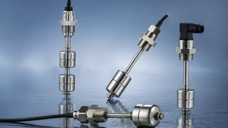
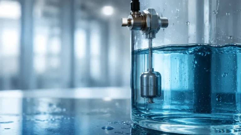
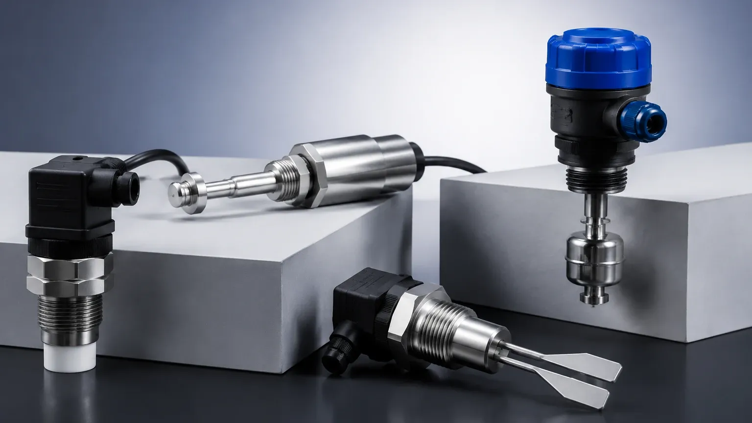
Magnetic level gauges are side-mounted to a vessel. They use a float containing a permanent magnet that moves with the liquid level inside a bypass chamber. Outside the chamber, a series of magnetic flags or a follower indicates the level visually. These are preferred for high-pressure or high-temperature applications where direct visual confirmation is required without the risks associated with glass sight gauges.
Point Level Detection vs. Continuous Gauging
While a level sensor gauge typically refers to a device providing a continuous output (e.g., 4-20mA or HART signal), many systems rely on Level Switches for critical safety functions.
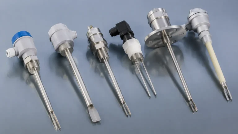
Level switches are point-level detectors that trigger an electrical contact when the material reaches a specific height. They are often used as redundant safety measures alongside continuous gauges to provide high-high (HH) or low-low (LL) alarms. Common technologies for level switches include vibrating forks, rotary paddles, and capacitive probes. In many industrial architectures, a continuous radar gauge provides the primary process data, while independent level switches provide the hard-wired interlocks for pump protection and spill prevention.
Technical Selection Criteria
Selecting a level sensor gauge is not a "one-size-fits-all" process. Engineers must evaluate the following parameters to ensure long-term reliability.
1. Media Properties
* Dielectric Constant ($ε_r$): Critical for radar and capacitive sensors. Low dielectric fluids (like oils) reflect less energy than high dielectric fluids (like water).
* Density: Critical for hydrostatic and buoyancy-based sensors (magnetic gauges).
* Viscosity and Coating: Highly viscous or sticky media can cause buildup on probes, necessitating non-contact solutions or self-cleaning designs.
* Corrosiveness: Requires specific materials of construction, such as PTFE, PVDF, or high-grade stainless steel.
2. Process Conditions
* Temperature: Standard sensors may operate up to 80°C (176°F), while specialized high-temperature versions can handle over 400°C (752°F).
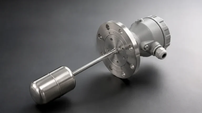
* Pressure: Vacuum conditions eliminate ultrasonic options, while high-pressure vessels (above 40 bar / 580 psi) require robust flange connections and specialized sensor housings.
* Turbulence and Foam: Heavy foam can absorb ultrasonic and radar signals. In these cases, Guided Wave Radar or hydrostatic sensors are often superior.
3. Tank Geometry
* Dead Zones: Every sensor has a "blocking distance" or dead zone at the top where it cannot measure. This must be accounted for in tank design.
* Obstructions: Internal pipes, agitators, and baffles can create false echoes for non-contact sensors.
Comparison Table: Level Measurement Technologies
| Technology | Accuracy | Media Type | Max Temp (Approx.) | Advantages | Limitations |
| :— | :— | :— | :— | :— | :— |
| Radar (80 GHz) | ±1 mm | Liquids/Solids | 200°C (392°F) | Non-contact, high precision | High initial cost |
| Guided Wave Radar | ±2 mm | Liquids/Slurries | 450°C (842°F) | Handles foam/steam well | Contacting probe (buildup) |
| Ultrasonic | ±0.25% Range | Liquids/Solids | 80°C (176°F) | Cost-effective, simple | Affected by vapor/vacuum |
| Hydrostatic | ±0.1% Span | Liquids | 100°C (212°F) | Simple installation | Sensitive to density shifts |
| Magnetic Gauge | ±5 mm | Liquids | 400°C (752°F) | Visual + Remote output | Side-mounting required |
Installation Considerations
Proper installation is as important as technology selection. Even the most advanced level sensor gauge will fail if installed incorrectly.
1. Nozzle Dimensions: For radar and ultrasonic sensors, the nozzle height and diameter must be within the manufacturer's specifications to prevent signal interference from the nozzle edge.
2. Orientation: Sensors should generally be installed perpendicular to the liquid surface. For solids, aiming flanges may be required to account for the angle of repose.
3. Stirrer Interference: If a tank has an agitator, the sensor should be positioned where the beam path does not intersect the blades. Modern radar software can "map out" these static reflections, but physical clearance is always preferred.
4. Venting: Hydrostatic sensors in sealed tanks require a differential pressure (DP) setup or a vented cable to compensate for changes in atmospheric or headspace pressure.
Common Risks and Limitations
Engineers should be aware of specific failure modes associated with level instrumentation:
* Signal Absorption: In ultrasonic applications, heavy steam or certain gas mixtures can change the speed of sound or absorb the pulse entirely, leading to a "loss of echo."
* Condensation and Buildup: On non-contact sensors, heavy condensation on the antenna can attenuate the signal. Using PTFE-faced antennas or air purging systems can mitigate this.
* Density Fluctuations: If a hydrostatic sensor is calibrated for water but the process fluid changes to a different chemical, the level reading will be incorrect. Continuous density monitoring or switching to radar may be necessary.
* Dielectric Shifts: If the dielectric constant of a liquid drops significantly, a radar sensor might "see through" the liquid to the tank bottom, providing a false low reading.
Frequently Asked Questions (FAQ)
Q: Can I use one level sensor gauge for both liquids and solids?
A: Some high-frequency radar sensors are versatile enough for both, but solids measurement typically requires sensors with higher power and specialized software to handle uneven surfaces and dust.
Q: What is the difference between a level transmitter and a level gauge?
A: Historically, a "gauge" referred to a local visual indicator (like a sight glass), while a "transmitter" sent an electronic signal to a control system. Today, the terms are often used interchangeably, with most modern gauges featuring digital transmitters.
Q: How often do level sensors need calibration?
A: This depends on the technology and the criticality of the process. Hydrostatic sensors may drift over time and require annual calibration. Radar sensors, being time-of-flight based, are extremely stable and often only require a functional check (proof test) rather than a full recalibration.
Q: Is Guided Wave Radar better than Non-Contact Radar?
A: Not necessarily. GWR is better for narrow tanks, low dielectric fluids, and foamy surfaces. Non-contact radar is better for corrosive media (as nothing touches the fluid) and applications where the tank must remain sealed without internal probes.
Conclusion
The selection of a level sensor gauge is a technical decision that impacts the safety and profitability of industrial operations. By understanding the physics of radar, ultrasonic, and hydrostatic measurement, and by accounting for the specific challenges of the media and vessel, engineers can implement robust solutions. For many systems, the integration of continuous gauging with secondary Level Switches remains the industry standard for comprehensive level management and overfill protection.