Level Switch Transmitter
Level Switch Transmitter
In the landscape of industrial process control, the distinction between point-level detection and continuous level measurement is fundamental. However, as automation requirements evolve, the industry has seen the rise of the level switch transmitter—a hybrid approach that combines the discrete signaling of a switch with the data-rich output of a transmitter. Understanding the nuances of these technologies is essential for engineers tasked with maintaining tank safety, optimizing inventory, and preventing costly overfills.
This guide examines the principles, selection criteria, and practical application of Level Switches and transmitters to help technical teams make informed procurement and installation decisions.
Understanding the Measurement Principles
Before selecting a level switch transmitter, it is necessary to understand the underlying physics used to detect the presence or volume of a medium. Most industrial devices fall into two categories: point-level detection and continuous measurement.
Point-Level Detection (Switches)
Point-level sensors are designed to detect when a substance reaches a specific height in a vessel. They provide a binary output (on/off) and are typically used for high-level alarms or low-level pump protection.
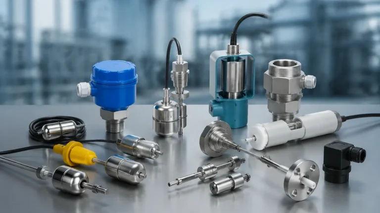
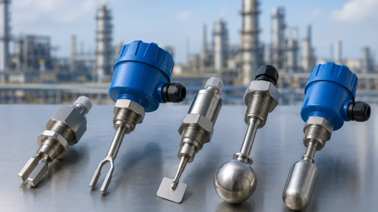
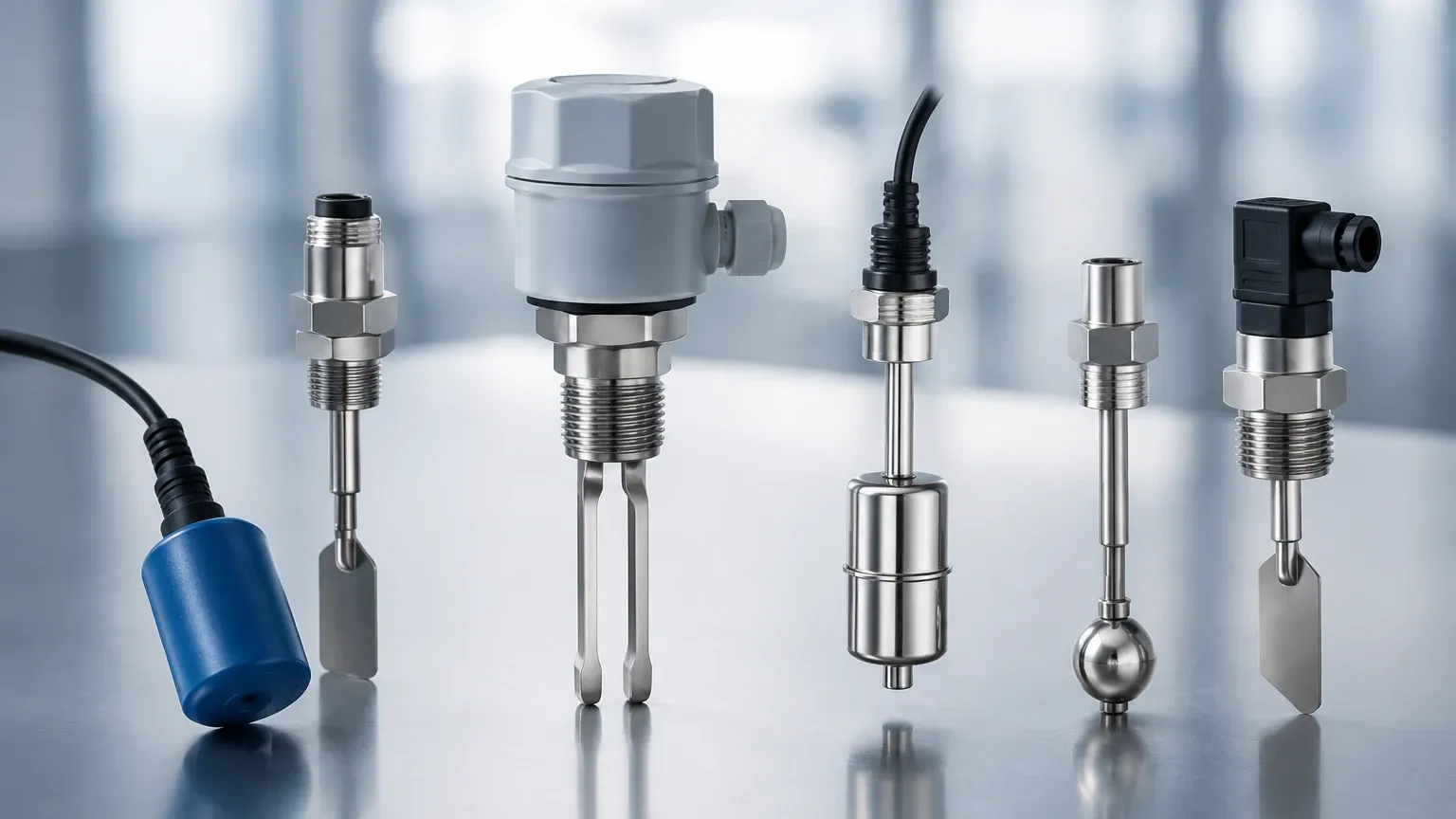
* Vibrating Tuning Fork: These devices use piezoelectric crystals to vibrate a fork at its natural frequency. When the fork is submerged in a liquid or solid, the frequency changes, triggering the switch. They are highly reliable and unaffected by flow, bubbles, or turbulence.
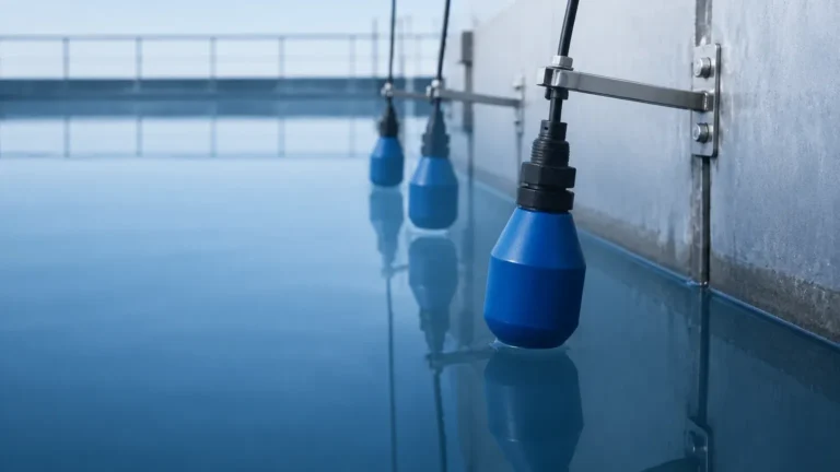
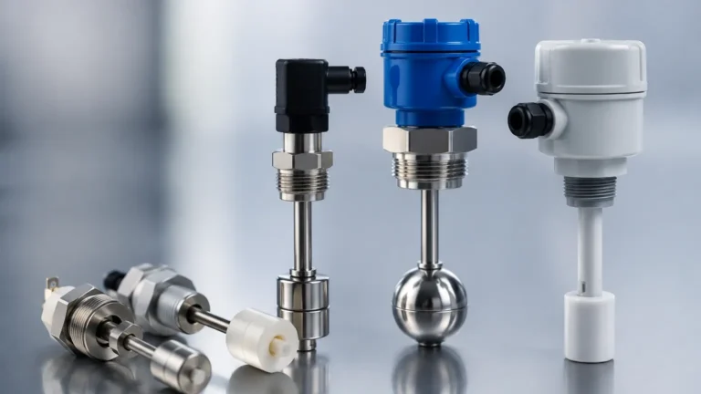
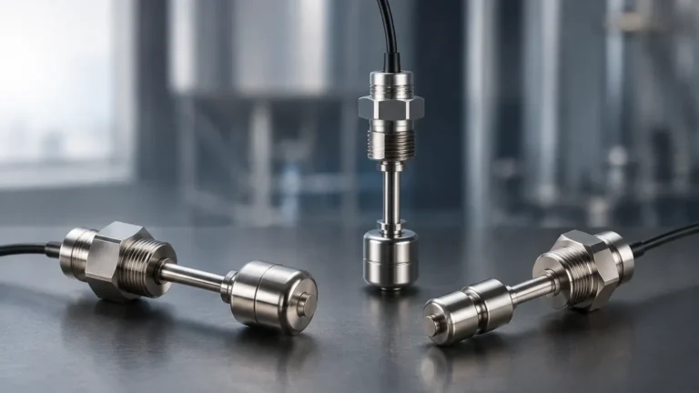
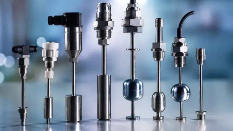
* Float Switches: A mechanical approach where a float containing a magnet moves with the liquid level. When it reaches a reed switch within the stem, the circuit closes or opens. These are cost-effective but susceptible to mechanical wear and coating.
* Capacitance Switches: These measure the change in capacitance between an electrode and the tank wall. They are excellent for detecting interfaces between different liquids but require calibration for specific dielectric constants.
Continuous Level Measurement (Transmitters)
Transmitters provide a constant signal (typically 4-20mA, HART, or Modbus) representing the exact level within a range.
* Radar (GWR and Non-Contact): Radar level meters emit electromagnetic pulses. Guided Wave Radar (GWR) uses a probe to direct the signal, while non-contact radar sends waves through the air. The time-of-flight (ToF) determines the distance. Radar is considered the gold standard for accuracy in challenging environments.
* Ultrasonic: Similar to radar but uses sound waves. It is non-contact and ideal for water treatment, though it can be affected by heavy foam, dust, or vacuum conditions.
* Hydrostatic: These sensors measure the pressure exerted by the liquid column. Since pressure is proportional to the height and density of the fluid, the transmitter can calculate the level accurately for vented or pressurized tanks.
The Functionality of a Level Switch Transmitter
A "level switch transmitter" typically refers to a device that provides continuous measurement data while also featuring integrated relay outputs or programmable switch points. In modern digital architectures, a continuous transmitter can act as a multi-point switch by assigning specific level percentages to different relay outputs in a PLC or directly on the device head.
This dual functionality offers several advantages:
1. Redundancy: A single device can provide a 4-20mA signal for process control and a dry contact for an emergency shutdown (ESD) loop.
2. Reduced Process Penetrations: Using one instrument for both switching and transmitting reduces the number of holes needed in a pressure vessel, lowering the risk of leaks.
3. Simplified Wiring: Digital protocols like HART allow the level switch transmitter to communicate multiple variables over a single pair of wires.
Practical Selection Table
Choosing the right technology depends on the physical properties of the medium and the environmental conditions of the tank.
| Technology | Media Type | Temp. Range | Pressure Range | Accuracy | Best Use Case |
| :— | :— | :— | :— | :— | :— |
| Vibrating Fork | Liquids/Solids | -50 to 250°C | Up to 64 bar | ±1 mm | Overfill protection, pump dry-run |
| Ultrasonic | Liquids/Slurries | -40 to 80°C | Up to 3 bar | ±0.25% FS | Water treatment, open channels |
| Radar (80GHz) | Liquids/Solids | -40 to 200°C | Up to 40 bar | ±2 mm | Chemical storage, narrow tanks |
| Hydrostatic | Liquids | -20 to 100°C | Up to 400m H2O | ±0.1% FS | Deep wells, fuel tanks |
| Magnetic Float | Clean Liquids | -40 to 150°C | Up to 40 bar | ±5 mm | Simple water tanks, oil sumps |
Installation Considerations
Correct installation is as critical as device selection. Even the most advanced level switch transmitter will fail if environmental factors are ignored.
1. The Blocking Distance (Dead Zone)
All top-mounted transmitters (Radar and Ultrasonic) have a "dead zone" directly beneath the sensor where measurement is impossible. For example, if an ultrasonic sensor has a 300mm (approx. 11.8 inches) blocking distance, the tank should never be filled above that point, or the sensor will provide an error or a false "full" reading.
2. Nozzle Geometry
When installing a level switch transmitter on a nozzle, the nozzle diameter and height must be considered. If the nozzle is too narrow and long, it can cause signal interference (ringing) for radar and ultrasonic waves. Generally, the nozzle should be as short as possible, and the sensor face should extend slightly into the tank if the technology allows.
3. Avoiding Obstructions
Internal tank structures such as agitators, heating coils, or ladders can create "false echoes." While modern software can perform a "false echo suppression" or "background subtraction," it is best practice to mount the device away from these obstructions. For radar, a distance of at least 200mm (7.8 inches) from the tank wall is usually recommended to avoid side-lobe interference.
4. Environmental Factors
* Foam: Heavy, dense foam can absorb ultrasonic and radar signals. In such cases, GWR or hydrostatic transmitters are preferred.
* Vapor and Condensation: Condensation on the sensor face can attenuate signals. High-frequency radar (80GHz) is generally more resistant to condensation than lower-frequency versions.
* Turbulence: If the liquid surface is highly turbulent, a stilling well or a bypass pipe may be required to provide a stable surface for measurement.
Limitations and Common Risks
While versatile, the level switch transmitter is not a universal solution. Engineers must be aware of the following limitations:
* Media Build-up: In applications involving sticky or viscous fluids (like resins or heavy crude), build-up on the probe of a GWR or the forks of a vibrating switch can lead to false positives. Non-contact methods are superior here.
* Dielectric Constant ($ε_r$): Radar and capacitance-based level switch transmitters rely on the dielectric constant of the material. If the $ε_r$ is too low (e.g., less than 1.4), the signal reflection may be too weak for standard non-contact radar, necessitating the use of a guided wave probe.
* Vacuum Conditions: Ultrasonic waves require a medium (air or gas) to travel. In a vacuum, ultrasonic sensors will not function, making radar or hydrostatic sensors the only viable options.
* Density Variations: Hydrostatic transmitters are sensitive to changes in liquid density. If the temperature of the fluid changes significantly, or if different fluids are stored in the same tank, the level reading will drift unless the system is compensated with a temperature sensor or a second pressure reference.
Frequently Asked Questions (FAQ)
Q: Can a level transmitter completely replace a mechanical level switch?
A: In many process control scenarios, yes. However, for critical safety functions (SIL-rated loops), it is often recommended to have a diverse technology mix—for example, using a radar transmitter for continuous control and a vibrating tuning fork switch for independent high-level protection.
Q: What is the difference between a 2-wire and a 4-wire level switch transmitter?
A: A 2-wire device is loop-powered, meaning the same two wires provide power and carry the 4-20mA signal. This is common for modern, low-power sensors. A 4-wire device has separate pairs for power (often 110/220V AC or 24V DC) and the signal output, which is typical for older units or devices requiring high power for heaters or high-intensity signals.
Q: How do I calibrate a level switch transmitter?
A: Most modern digital transmitters are calibrated via a local display, a handheld HART communicator, or PC software. Calibration involves setting the "4mA point" (usually the bottom of the tank/0% level) and the "20mA point" (the top of the tank/100% level). Physical calibration with actual fluid is preferred but "dry calibration" using calculated distances is common for radar and ultrasonic units.
Q: Is it better to use a top-mounted or side-mounted sensor?
A: Top-mounted sensors (Radar, Ultrasonic) are generally preferred because they do not come into contact with the medium as much as side-mounted sensors and are easier to maintain without draining the tank. Side-mounted sensors (like certain magnetic switches or hydrostatic sensors) are used when overhead space is limited or for specific pressure-based measurements.
Conclusion for Engineering Teams
The integration of switching and transmitting capabilities into a single instrument has streamlined industrial level measurement. When selecting a level switch transmitter, the priority should always be the compatibility between the measurement principle and the physical properties of the medium. By considering factors like the dielectric constant, potential for foam, and tank geometry, engineers can ensure high accuracy and long-term reliability.
For complex applications, consulting with a manufacturer that offers a broad portfolio—from radar level meters to robust Level Switches—is the most effective way to guarantee that the chosen solution meets the specific safety and operational requirements of the facility.