Level 8 Switch
Level 8 Switch
In the landscape of industrial automation and process control, the ability to monitor multiple points within a single vessel is critical for safety, efficiency, and inventory management. While standard point level sensors often handle high or low alarms, more complex operations require high-density monitoring. The concept of a level 8 switch—typically referring to an 8-point multi-level switch or an 8-channel level controller—provides the granularity needed for sophisticated pump sequencing, tiered alarms, and precise batching processes.
Reliable Level Switches serve as the primary defense against tank overfills and dry-run conditions for pumps. When configured for multiple detection points, these instruments allow engineers to map the contents of a tank with significantly higher resolution than a simple binary "full or empty" signal.
Measurement Principles for Multi-Point Detection
Before selecting a level 8 switch configuration, it is essential to understand the underlying measurement technologies. Different physical principles are suited to different media, ranging from potable water to corrosive chemicals and granular solids.
Float-Based Buoyancy
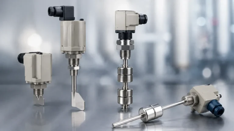
Float switches are the most traditional form of multi-point level detection. They operate on the principle of buoyancy, where a magnetic float moves along a stem as the liquid level rises or falls. Inside the stem are reed switches positioned at specific heights. When the magnet in the float passes a reed switch, it closes (or opens) the circuit. For a level 8 switch application, a single long stem can house up to eight individual reed switches, providing eight distinct digital outputs from one process connection.
Tuning Fork (Vibrational) Switches
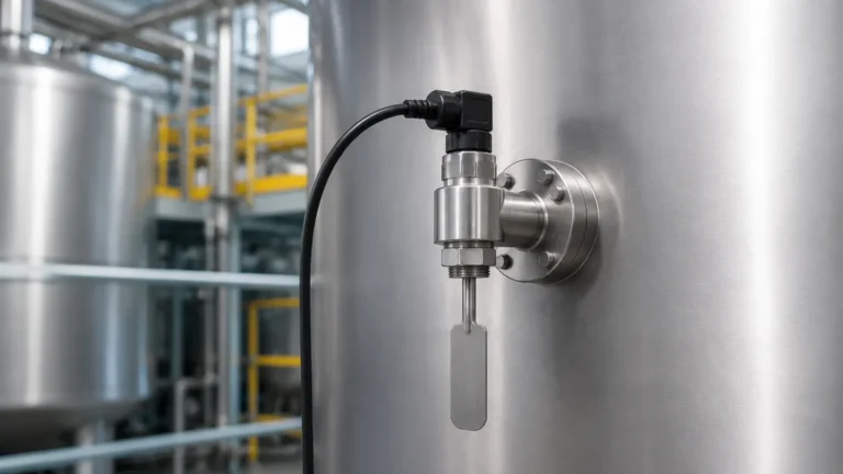
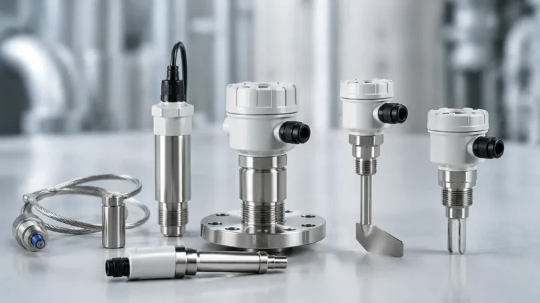
Vibrating level switches utilize a piezoelectric crystal to energize a tuning fork at its natural frequency. When the fork is covered by the medium (liquid or solid), the frequency shifts or the vibration is damped. This change is detected by the electronics and converted into a switching signal. While these are typically single-point devices, they are often used in arrays or connected to an 8-channel controller to manage complex logic across multiple vessels or stages.
Capacitance Level Switches
Capacitance switches measure the change in electrical capacitance between the sensor probe and the tank wall (or a reference electrode). As the medium displaces air, the dielectric constant changes, triggering the switch. These are highly effective for detecting the interface between two different liquids or for monitoring sticky substances that might foul a mechanical float.
Ultrasonic and Optical Sensors
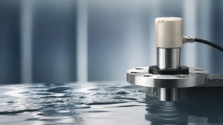
Non-contact or gap-style sensors use sound waves or light refraction to detect the presence of a medium. In multi-point configurations, these are often deployed in a manifold or as part of a high-density sensor array where physical contact with the media must be minimized to prevent contamination or corrosion.
The Role of the Level 8 Switch in Process Control
Integrating an 8-point switching system allows for more nuanced control than standard dual-point (High/Low) systems. In a typical industrial application, the eight points might be allocated as follows:
1. L1 (Level 1): Extreme Low / Dry-run protection for pumps.
2. L2 (Level 2): Low-level alarm to trigger refill.
3. L3-L6: Intermediate steps for pump sequencing or variable speed drive (VSD) adjustment.
4. L7: High-level alarm to stop inflow.
5. L8: Emergency High / Overfill prevention to shut down the entire system.
By utilizing a level 8 switch configuration, operators can implement "lead-lag" pump logic, where multiple pumps are brought online or offline depending on the specific level reached, ensuring even wear on equipment and optimal flow rates.
Technical Selection Criteria
Choosing the correct multi-point level switch requires a thorough analysis of the process environment. Engineers should consult the following table to compare common technologies used in high-density switching applications.
Technology Comparison Table
| Feature | Magnetic Float | Tuning Fork | Capacitance | Ultrasonic Gap |
| :— | :— | :— | :— | :— |
| Media Type | Clean Liquids | Liquids / Solids | Liquids / Slurries | Clean Liquids |
| Max Points | Up to 8+ per stem | Single (requires array) | Single or Dual | Single (requires array) |
| Viscosity Limit | Low to Medium | High | High | Low |
| Pressure Range | Up to 40 bar (4.0 MPa) | Up to 64 bar (6.4 MPa) | Up to 100 bar (10 MPa) | Up to 20 bar (2.0 MPa) |
| Temp. Range | -20°C to 150°C | -50°C to 250°C | -40°C to 200°C | -40°C to 100°C |
| Maintenance | Low (Mechanical) | Very Low | Moderate (Coating) | Low |
Key Evaluation Factors
1. Media Density and Specific Gravity: For float-based level 8 switch systems, the float must be lighter than the liquid. If the specific gravity is too low (e.g., < 0.5), specialized high-buoyancy floats are required.
2. Chemical Compatibility: The wetted materials (316L Stainless Steel, PP, PVDF, or PTFE) must be resistant to the process media to prevent premature failure.
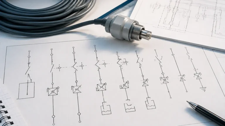
3. Output Requirements: Do you require individual SPST/SPDT contacts for each of the eight points, or a digital bus output (like Modbus or HART) that transmits the status of all points over a single pair of wires?
4. Mounting Constraints: Multi-point switches often require larger flange sizes (e.g., DN50 or 2" ANSI) to accommodate the floats and the wiring for eight separate points.
Installation and Positioning Considerations
Proper installation is paramount for the accuracy of a level 8 switch. Because these devices often monitor critical safety thresholds, the following guidelines should be followed:
* Avoid Turbulence: Do not install the switch directly in the path of an inlet flow. Turbulence can cause float chatter or false triggers in tuning fork sensors. If turbulence is unavoidable, a stilling well (a perforated pipe surrounding the sensor) should be used.
* Minimum Distance Between Points: In multi-point float switches, there is a physical limit to how close the reed switches can be placed. Typically, a minimum distance of 50mm (approx. 2 inches) is required between switching levels to prevent magnetic interference between the floats.
* Vertical Alignment: Float-based switches must be installed within 30° of vertical to ensure the floats move freely along the stem. For high-precision applications, a perfectly vertical orientation is recommended.
* Wiring and Grounding: With eight points of detection, the wiring harness can become complex. Ensure that all cables are shielded and properly grounded to prevent electromagnetic interference (EMI) from nearby motors or heavy machinery.

Common Risks and Limitations
While a level 8 switch provides detailed data, there are inherent risks in complex point-level systems:
* Mechanical Fouling: In float-based systems, buildup of calcium, fats, or oils can cause the floats to stick. Regular inspection and cleaning are necessary in "dirty" applications.
* Dielectric Sensitivity: Capacitance switches may require recalibration if the moisture content or chemical composition of the media changes significantly, as this affects the dielectric constant.
* False Triggers from Foam: Tuning forks and ultrasonic sensors can sometimes be fooled by heavy foam on the surface of a liquid. In such cases, a float switch or a specialized capacitance probe may be more reliable.
* Complexity of Troubleshooting: Diagnosing a failure in an 8-point system requires systematic testing of each circuit. Using a controller with built-in diagnostics can significantly reduce downtime.
Practical Engineering Maintenance
To ensure the longevity of Level Switches in a multi-point configuration, a preventative maintenance schedule should be established.
1. Monthly Visual Inspection: Check for signs of corrosion on the housing and process connection. Ensure that cable glands are tight and moisture has not entered the terminal enclosure.
2. Quarterly Function Test: Manually raise the level (or move the floats) to verify that each of the eight points triggers the correct alarm or control logic in the PLC/DCS.
3. Annual Calibration Check: For electronic switches (Capacitance/Ultrasonic), verify that the trigger points have not drifted due to electronic aging or environmental changes.
Frequently Asked Questions (FAQ)
Q: Can I use a level 8 switch for both liquids and solids?
A: It depends on the technology. Magnetic float switches are strictly for liquids. Tuning fork and capacitance switches can be used for solids, but they are typically single-point devices. To achieve eight points in solids, you would usually install eight separate sensors at different heights.
Q: What is the maximum length for a multi-point float switch stem?
A: Most manufacturers can produce stems up to 4 meters (approx. 13 feet). For lengths exceeding 2 meters, support brackets or stilling wells are recommended to prevent the stem from bending due to fluid movement.
Q: How do I handle hazardous environments with an 8-point switch?
A: In explosive atmospheres (Ex zones), you must use intrinsically safe (IS) barriers or explosion-proof enclosures. Since a level 8 switch has multiple circuits, each circuit must be protected, or a single multi-channel IS barrier must be used.
Q: Is it possible to adjust the switching points after installation?
A: For most multi-point float switches, the reed switches are fixed inside the stem and cannot be moved. If adjustability is required, you should opt for a system where individual sensors are mounted on a track or use a continuous level transmitter with programmable switching outputs.
Conclusion
The implementation of a level 8 switch system offers a robust solution for high-resolution point level monitoring. By understanding the physical principles of the sensors and the specific requirements of the process media, engineers can design a system that enhances both safety and operational efficiency. Whether using a multi-float stem or an array of vibrational switches, the key to success lies in careful selection, precise installation, and a commitment to regular maintenance. For those looking to optimize their vessel management, exploring advanced Level Switches is the first step toward a more controlled and predictable industrial process.