Level Sensor Yellow
Level Sensor Yellow
In the complex landscape of industrial automation and process control, visual indicators and color-coding play a pivotal role in operational safety and efficiency. The term "level sensor yellow" frequently arises in technical discussions regarding the status indication, housing specifications, or wiring standards of point-level detection devices. Understanding why a sensor displays a yellow signal—or why a yellow-housed sensor is specified for a particular environment—is essential for engineers and maintenance teams working with modern Level Switches.
This guide examines the technical principles of level measurement, the specific significance of yellow indicators in industrial instrumentation, and the criteria for selecting the appropriate level switch technology for various process applications.
Measurement Principles of Level Switches
Before selecting a device based on its visual indicators or housing color, it is fundamental to understand how different level switches interact with the process media. Level switches are point-level detection devices that provide a discrete output (typically a relay or transistor signal) when a material reaches a specific height in a tank, silo, or pipe.
1. Vibrating Tuning Fork Principle
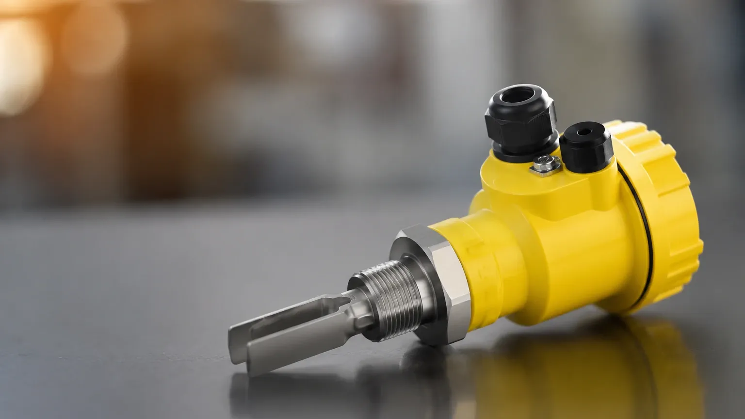
A tuning fork level switch utilizes an electronic circuit to energize a fork-shaped sensing element, causing it to vibrate at its natural resonant frequency in the air. When the process media (liquid or solid) covers the fork, the frequency of vibration changes or the vibration is dampened entirely. The internal electronics detect this shift and toggle the output state. This technology is highly reliable as it is largely unaffected by turbulence, bubbles, or foam.
2. Ultrasonic Point Level Detection
Ultrasonic level switches operate on the principle of acoustic wave propagation. A transducer emits high-frequency sound pulses. In a gap-style ultrasonic switch, the signal is transmitted across a small gap. When liquid fills the gap, the ultrasonic signal passes through efficiently; when the gap is empty (filled with air or gas), the signal is attenuated. This change in signal strength triggers the switch.
3. Float and Magnetic Principles
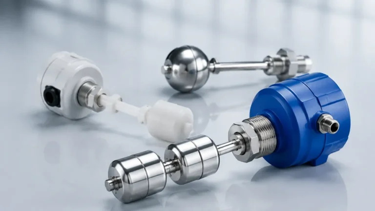
Float switches rely on buoyancy. A float containing a permanent magnet moves up and down a stem as the liquid level rises and falls. Inside the stem, a reed switch or a Hall-effect sensor is positioned at a specific point. When the magnet in the float reaches the switch, the magnetic field closes or opens the circuit. This is a purely mechanical-to-electrical interface, making it a cost-effective solution for clean, non-coating liquids.
4. Capacitive Level Sensing
Capacitive switches measure the change in electrical capacitance between the sensor probe and the tank wall (or a reference electrode). Every material has a dielectric constant. As the media displaces air around the probe, the capacitance increases. Once the capacitance crosses a pre-set threshold, the sensor changes its output state. This method is effective for detecting powders, granulates, and liquids, though it may require calibration for different materials.
The Significance of Yellow in Level Instrumentation
When an operator refers to a "level sensor yellow," they are typically describing one of three technical attributes: the status LED, the physical housing, or the electrical wiring.
Visual Status Indicators (LEDs)
Most modern level switches, including those manufactured by Welk, feature integrated LED indicators for local diagnostics. In standard industrial logic:
* Green: Indicates that the device is powered and functioning correctly (Power OK).
* Yellow: Typically indicates the "Switching State." For a Normally Open (NO) configuration, a yellow LED illuminates when the sensor detects the material and the output is active. For a Normally Closed (NC) configuration, the yellow LED may turn off when the material is detected.
* Red: Generally signifies a fault condition, such as a short circuit, sensor failure, or a high-level alarm state in safety-critical systems.
Housing and Cable Color-Coding
In certain industries, yellow housings or yellow PVC-jacketed cables are used to denote specific functional categories. For example:
* High Visibility: Yellow housings are often used in dark or congested industrial environments to help maintenance personnel quickly locate the sensor.
* Safety and Communication: Some manufacturers use yellow to distinguish sensors equipped with specific communication protocols, such as AS-Interface (AS-i) or certain safety-rated BUS systems.
* Chemical Resistance: Yellow-coated sensors may indicate a specific material treatment, such as a PTFE or specialized polymer coating designed for corrosive environments.
Practical Selection Table
Choosing the right technology requires balancing the physical properties of the media with the environmental conditions of the installation site. The following table provides a comparison of common level switch technologies.
| Technology | Suitable Media | Max Pressure (Typical) | Max Temp (Typical) | Key Advantage |
| :— | :— | :— | :— | :— |
| Vibrating Fork | Liquids, Powders, Slurries | 40 bar (4.0 MPa) | 150°C | No calibration required; ignores foam. |
| Ultrasonic | Clean Liquids, Acids | 10 bar (1.0 MPa) | 80°C | Non-contact or gap-style available. |
| Float Switch | Water, Oil, Non-coating | 20 bar (2.0 MPa) | 120°C | Simple, low-cost, no power needed for reed type. |
| Capacitance | Solids, Liquids, Pastes | 25 bar (2.5 MPa) | 200°C | Can detect through non-metallic walls. |
| Hydrostatic | Water, Wastewater | 100 bar (10 MPa) | 80°C | Excellent for deep wells and large tanks. |
Installation Considerations
Proper installation is critical to ensuring that the "level sensor yellow" indicator accurately reflects the process state. Incorrect mounting can lead to false triggers or premature sensor failure.
1. Avoid Turbulence: Level switches should not be installed directly in the path of a fill stream. The kinetic energy of the incoming material can cause mechanical damage or erratic switching. If the sensor must be near an inlet, a baffle plate should be installed.
2. Orientation:
* *Tuning Forks:* Should be oriented so that the flat surfaces of the forks are parallel to the flow of the liquid to prevent material buildup between the tines.
* *Float Switches:* Must be mounted vertically (for top-mount) or horizontally (for side-mount) within the specified angle tolerances (usually ±30°).
3. Nozzle Length: For ultrasonic and capacitive sensors, the mounting nozzle should be as short as possible. Long nozzles can create "dead zones" or internal reflections that interfere with the sensor's ability to detect the actual level in the tank.
4. Cable Glands and Drip Loops: Always ensure that cable glands are tightened to maintain the IP rating (e.g., IP65 or IP67). Use a drip loop in the cabling to prevent moisture from traveling down the wire and entering the sensor housing.
Limitations and Maintenance
While level switches are designed for durability, they are not universal solutions. Each technology has specific limitations:
* Coating and Buildup: Capacitive and tuning fork sensors can struggle if the media is highly viscous and leaves a thick coating on the probe. In such cases, a sensor with "active shield" technology or a self-cleaning vibration frequency may be required.
* Specific Gravity: Float switches are dependent on the density of the liquid. If the liquid density drops below the float's design specification (e.g., < 0.7 g/cm³), the float will not rise.
* Vacuum Conditions: Ultrasonic sensors rely on air or gas to transmit sound. In a vacuum, standard ultrasonic level switches will not function.
Maintenance Checklist:
* Monthly: Check the status LED. If the "level sensor yellow" light is flickering, it may indicate an intermittent electrical connection or a level fluctuating near the switching point (hysteresis).
* Quarterly: Inspect the sensing element for corrosion or material buildup. Clean with a soft cloth or appropriate solvent if necessary.
* Annually: Verify the switching point by manually raising the level or removing the sensor for a bench test.
Frequently Asked Questions (FAQs)
Q: Why is my level sensor's yellow LED blinking?
A: A blinking yellow LED often indicates a marginal signal or a diagnostic warning. In some digital level switches, this may signify that the sensor is detecting an object but the signal strength is below the optimal threshold, or that the device is in "teach mode."
Q: Can I use a yellow-housed sensor in an explosive atmosphere?
A: The color of the housing does not determine the safety rating. You must check the device's nameplate for ATEX, IECEx, or UL certifications. While some manufacturers use specific colors for safety lines, the formal certification (e.g., Ex ia IIC T6) is the only authoritative guide.
Q: Does the yellow wire in the sensor cable always mean the same thing?
A: No. While many M12 4-pin cables follow the Brown (+), Blue (-), Black (Out), and White (Out 2) standard, older or proprietary cables may use yellow for ground (PE) or a specific alarm output. Always consult the wiring diagram provided by the manufacturer.
Q: How do I choose between a Normally Open and Normally Closed level switch?
A: This depends on your fail-safe requirements. For high-level alarms (overfill prevention), a Normally Closed (NC) circuit is often preferred because the circuit will open (triggering the alarm) if the wire is accidentally cut or power is lost.
For professional-grade measurement solutions, Welk offers a comprehensive range of instruments tailored to specific industrial needs. Whether you require high-pressure resistance for oil and gas or sanitary designs for food processing, selecting the right Level Switches ensures long-term reliability and process safety.