Pneumatic Level Switches
Pneumatic Level Switches
In the landscape of industrial automation, level measurement is a critical pillar for safety, efficiency, and process control. While electronic sensors dominate many modern facilities, pneumatic level switches remain indispensable in specific environments. These mechanical-pneumatic hybrids provide a robust solution for level detection where electrical power is unavailable, undesirable, or hazardous. As a professional manufacturer, Welk provides a range of Level Switches designed to meet the rigorous demands of the oil and gas, chemical processing, and water treatment industries.
This guide explores the engineering principles, selection criteria, and practical application of pneumatic level switches, offering a technical reference for engineers tasked with managing fluid levels in challenging environments.
Fundamental Principles of Pneumatic Level Detection
Before selecting a specific model, it is essential to understand the underlying physics that allow a pneumatic device to detect liquid levels. Unlike electronic switches that use conductivity or capacitance, pneumatic level switches rely on the interaction between mechanical displacement and air pressure. The primary function is to convert a change in liquid level into a discrete pneumatic signal, typically used to actuate valves, pumps, or alarms.
The Flapper-Nozzle Mechanism
The most common principle used in pneumatic point-level detection is the flapper-nozzle assembly. In this system, a constant supply of compressed air—often referred to as instrument air—is fed toward a small nozzle. A mechanical component, such as a float or a diaphragm, is linked to a "flapper."
As the liquid level rises, the float moves upward, causing the flapper to move closer to the nozzle. This restricts the airflow, increasing the backpressure within the sensing line. Once this pressure reaches a predetermined threshold, it triggers a pilot valve. Conversely, as the level falls, the flapper moves away, the pressure drops, and the pilot valve resets. This mechanism allows for a binary "on/off" pneumatic output (e.g., 0 bar to 1.4 bar / 0 psi to 20 psi).
Snap-Action vs. Throttling Pilots
Pneumatic level switches generally utilize two types of pilot actions:
1. Snap-Action: This design ensures a rapid transition between states. It is ideal for high or low-level alarms where a definitive signal is required to prevent tank overflow or pump cavitation. The snap-action prevents "hunting" or fluttering of the output signal near the set point.
2. Throttling (Proportional): While less common for simple switches, some pneumatic level controllers provide an output pressure proportional to the level change. This is typically used in pneumatic control loops rather than simple point-level switching.
Key Components and Construction Materials
The reliability of pneumatic level switches in harsh environments depends heavily on their construction. Because these devices often come into direct contact with corrosive or high-pressure media, material selection is paramount.
The Sensing Element (Float or Displacer)
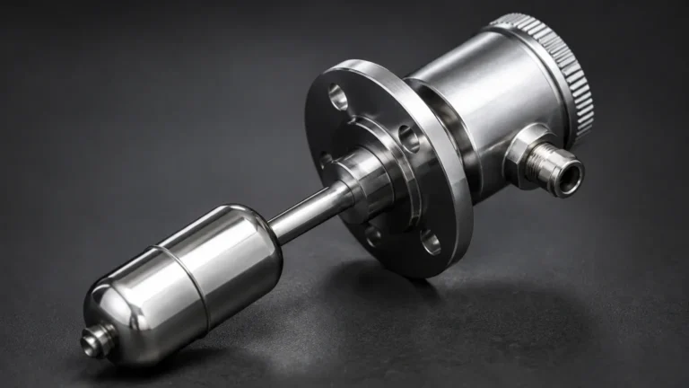
The float is the primary interface with the process media. It must be buoyant enough to move the mechanical linkage but strong enough to withstand process pressures. Common materials include:
* 316 Stainless Steel: The standard for most industrial water and chemical applications.
* Monel or Hastelloy: Utilized in highly corrosive environments, such as those involving sour gas (H2S) or strong acids.
* Polypropylene: Used for low-pressure, low-temperature applications involving aggressive chemicals where metals might fail.
The Housing and Pilot Valve
The housing protects the internal pneumatic components from the atmosphere. In offshore or coastal environments, housings are typically made of salt-resistant aluminum or stainless steel. The pilot valve, which manages the air signal, contains O-rings and seals. These seals must be compatible with both the instrument air (which may contain trace lubricants) and the ambient temperature. Viton (FKM) and Nitrile (NBR) are the most frequent choices, with Kalrez (FFKM) reserved for extreme chemical or thermal conditions.
Comparing Pneumatic vs. Electronic Level Switches
When designing a level control system, engineers must decide between pneumatic and electronic architectures. Each has distinct advantages depending on the site infrastructure.
| Feature | Pneumatic Level Switches | Electronic Level Switches |
| :— | :— | :— |
| Power Source | Compressed Air (Instrument Air) | Electricity (DC/AC) |
| Hazardous Areas | Inherently safe; no sparking risk | Requires Explosion-Proof or I.S. barriers |
| Signal Distance | Limited by air friction/latency | Long-distance (4-20mA, Modbus) |
| Maintenance | Mechanical wear, air leaks | Component aging, sensor fouling |
| Cost | Higher initial unit cost; lower wiring cost | Lower unit cost; higher installation cost |
Advantages of Pneumatic Logic
The primary advantage of pneumatic level switches is their inherent safety. In "Zone 0" or "Class I, Div 1" environments where explosive gases are constantly present, a pneumatic switch eliminates the risk of electrical sparking. Furthermore, in remote locations—such as upstream oil wellheads—where electrical infrastructure is non-existent, the availability of pressurized gas or air makes pneumatic switches the only viable choice.
Selection Criteria and Technical Specifications
Selecting the correct pneumatic level switch requires a detailed analysis of the process conditions. Failure to account for media density or pressure can lead to inaccurate switching or mechanical failure.
Specific Gravity (SG)
The buoyancy of a float is dependent on the density of the liquid. Most pneumatic level switches are calibrated for water (SG 1.0). If the media is a light hydrocarbon (SG 0.6 to 0.7), a larger float or a different linkage ratio may be required to ensure the flapper moves sufficiently to trigger the nozzle.
Process Pressure and Temperature
Pneumatic switches are often used in pressurized vessels. It is vital to ensure the float will not collapse under the maximum vessel pressure. Standard floats may be rated up to 50 bar (725 psi), while high-pressure versions can exceed 100 bar. Temperature ratings are equally critical; while the mechanical linkage can handle high heat, the pneumatic seals in the pilot valve often have a limit of 150°C to 200°C.
Technical Selection Matrix
| Parameter | Standard Industrial | High Pressure/Heavy Duty |
| :— | :— | :— |
| Max Pressure | 20 bar (290 psi) | 100+ bar (1450+ psi) |
| Temperature Range | -20°C to 120°C | -50°C to 250°C |
| Air Supply | 1.4 to 2.1 bar (20-30 psi) | Up to 7 bar (100 psi) |
| Connection Size | 1" to 2" NPT/Flanged | 3"+ Flanged |
| Wetted Materials | 316L SS | Hastelloy C276 / Monel |
Installation and Commissioning Guidelines
Proper installation is the most significant factor in the longevity of a pneumatic level switch. Because these are mechanical devices, they are sensitive to orientation and the quality of the air supply.
Mounting Orientation
Most pneumatic level switches are designed for horizontal mounting through the side of a tank. The internal pivot mechanism relies on gravity to return the float to its neutral position. If the switch is tilted even by a few degrees, the friction in the linkage may increase, leading to sticking or delayed response. Always use a spirit level during installation to ensure the device is perfectly horizontal or vertical as specified by the manufacturer.
Air Supply Quality
The "Achilles' heel" of any pneumatic system is contaminated air. Moisture, oil, and particulates can clog the fine nozzle of the flapper-nozzle assembly.
* Filtration: A 5-micron filter-regulator should be installed immediately upstream of the switch.
* Drying: In cold climates, moisture in the air lines can freeze, completely blocking the signal. Use desiccant or refrigerated dryers to maintain a dew point below the minimum ambient temperature.
Calibration Steps
1. Zeroing: With the tank empty (or level below the float), adjust the nozzle position until the output pressure is zero.
2. Span Check: Slowly raise the liquid level (or manually lift the float) and observe the pressure gauge. The switch should "snap" to the full supply pressure at the desired set point.
3. Hysteresis Adjustment: Some high-end Level Switches allow for adjustment of the deadband (the difference between the trip point and the reset point). This is useful in turbulent tanks to prevent rapid cycling.
Operational Limitations and Maintenance
While pneumatic switches are robust, they are not "set and forget" devices. They require periodic inspection to ensure the mechanical and pneumatic paths remain clear.
Common Risks
* Paraffin or Scale Buoyancy: In oil applications, paraffin wax can build up on the float, increasing its weight and changing the trip point. Regular cleaning of the wetted parts is necessary.
* Vibration: Excessive piping vibration can cause wear on the mechanical pivots and potentially lead to premature failure of the flapper linkage.
* Air Leaks: Even a small leak in the output signal line can cause a pressure drop that prevents the end device (like a valve actuator) from functioning correctly.
Maintenance Checklist
* Monthly: Drain the filter-regulator bowls of any collected moisture or oil.
* Quarterly: Perform a functional test by manually tripping the float to ensure the pneumatic signal reaches the control room or end-element.
* Annually: Inspect O-rings and seals for signs of brittleness or cracking. Replace the pilot valve internals if the switch has been in high-cycle service.
Frequently Asked Questions (FAQs)
Q: Can pneumatic level switches be used with hazardous gases as the supply medium?
A: Yes, in many upstream oil and gas applications, processed natural gas is used instead of compressed air to power the switches. However, the switch must be designed for "gas-bleed" operation, and the exhausted gas must be safely vented or recovered to prevent environmental hazards or fire risks.
Q: What is the maximum distance a pneumatic signal can travel?
A: Unlike electrical signals, pneumatic signals suffer from significant latency over long distances. For a standard 6mm (1/4") signal line, the practical limit is usually 30 to 50 meters. Beyond this, the time delay for the pressure to build up or bleed off becomes unacceptable for safety-critical applications.
Q: How do I handle turbulent liquid surfaces?
A: Turbulence can cause the float to bounce, leading to a noisy pneumatic signal. The best solution is to install the pneumatic level switch inside a "stilling well" or "external chamber." This isolates the float from surface waves while allowing the level to equalize through small holes in the bottom of the well.
Q: Are there pneumatic switches for dry bulk solids?
A: While most pneumatic switches are float-based for liquids, there are specialized diaphragm-type pneumatic switches used for powders and grains. These rely on the pressure of the solid material against a flexible diaphragm to block the internal air nozzle.
By understanding these technical nuances, engineering teams can effectively integrate pneumatic level switches into their process safety systems. Whether used as a primary control or a redundant backup to electronic sensors, these devices remain a cornerstone of reliable level management in the world's most demanding industrial environments. For further technical specifications and product variations, exploring the dedicated range of Level Switches is recommended to find the best fit for specific application parameters.