Level Switch Wiring Diagram
Level Switch Wiring Diagram
In industrial automation and process control, level switches serve as critical components for point-level detection. These devices provide discrete signals to indicate whether a liquid or solid has reached a specific height within a vessel. Understanding a level switch wiring diagram is essential for electrical engineers and maintenance technicians to ensure system reliability, prevent overfill conditions, and protect equipment from dry-running.
This guide examines the fundamental principles of level switch operation, the interpretation of wiring diagrams across different technologies, and practical installation considerations for industrial environments.
Core Principles of Point-Level Measurement
Before analyzing a wiring diagram, it is necessary to understand the physical principles that govern how different Level Switches detect the presence of a medium. The electrical output of a switch is directly linked to its sensing mechanism.
Float Level Switches
Float switches operate on the principle of buoyancy. A float containing a permanent magnet moves with the liquid level. When the float reaches a predetermined point, the magnetic field actuates a reed switch or a microswitch located within the stem or housing. These are typically "dry contact" devices, meaning they do not require external power to function, though they may have voltage and current limits for the signal they carry.
Tuning Fork (Vibrating) Level Switches
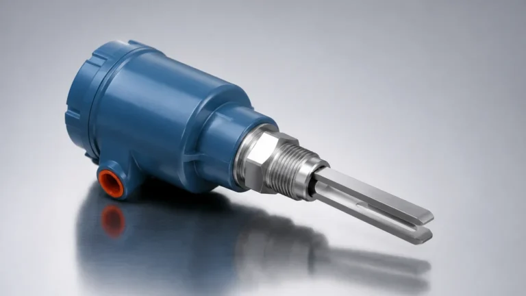
The sensing element of a tuning fork switch vibrates at its natural resonant frequency using piezoelectric crystals. When the fork is submerged in a liquid or covered by a solid, the frequency changes or the vibration is dampened. An internal electronic circuit detects this shift and changes the state of the output. These switches require a continuous power supply (typically 24V DC or 110/220V AC) to maintain the vibration.
Capacitive Level Switches
Capacitive switches measure the change in capacitance between a probe and the tank wall (or a reference electrode). As the medium displaces air, the dielectric constant changes, altering the capacitance. The electronics convert this change into a switching signal. Like tuning fork switches, these are active devices requiring a dedicated power input.
Standard Components of a Level Switch Wiring Diagram
A level switch wiring diagram typically illustrates three main segments: the power supply, the sensing circuit, and the output contact configuration. Understanding these symbols is the first step in successful integration.
Terminal Designations
* L / N (or + / -): These terminals are for the input power supply. In DC systems, polarity must be observed (e.g., +24V DC and 0V). In AC systems, L (Line) and N (Neutral) are used.
* COM (Common): The shared terminal for the output switch.
* NO (Normally Open): The contact remains open when the switch is in its "shelf state" (usually defined as the absence of the medium for a high-level alarm).
* NC (Normally Closed): The contact remains closed in the shelf state.
* PE (Protective Earth): The grounding terminal for safety and noise reduction.
Contact Logic: NO vs. NC
In industrial wiring, the terms "Normally Open" and "Normally Closed" refer to the state of the switch when it is not energized or not actuated. However, for level switches, it is crucial to confirm whether the diagram refers to the "dry" state or the "wet" state. Most manufacturers define the normal state as the condition where the switch is not submerged.
Wiring Configurations for Common Level Switch Types
Different technologies require specific wiring approaches. The following sections detail the most common configurations found in industrial applications.
1. Two-Wire AC/DC Switches
Two-wire switches are often used in series with a load (such as a relay coil or a PLC input). They act like a traditional light switch.
* Wiring: The power source, the level switch, and the load are connected in a single loop.
* Limitation: These switches often have a small "leakage current" even when in the OFF state to keep the internal electronics powered. This must be lower than the drop-out current of the connected relay to avoid false triggers.
2. Three-Wire DC (PNP/NPN) Switches
Electronic switches like capacitive or ultrasonic types often use transistor outputs.
* PNP (Sourcing): The switch connects the output terminal to the positive rail (+V) when activated. The load must be connected between the output and the negative rail (0V).
* NPN (Sinking): The switch connects the output terminal to the negative rail (0V) when activated. The load must be connected between the output and the positive rail (+V).
* Wiring Diagram Note: A three-wire diagram will show +V (Brown), 0V (Blue), and Signal (Black).
3. Relay Output (SPDT and DPDT)
Many industrial level switches provide a volt-free relay contact, which offers the greatest flexibility for interfacing with different voltages.
* SPDT (Single Pole Double Throw): Features three terminals (COM, NO, NC). It can control one circuit.
* DPDT (Double Pole Double Throw): Features six terminals (two sets of COM, NO, NC). This allows the switch to trigger two independent circuits simultaneously—for example, one for a local alarm light and one for a PLC input.
Level Switch Selection and Wiring Specification Table
When reviewing a level switch wiring diagram, use the following table to match the electrical requirements with the application needs.
| Feature | Float Switch | Tuning Fork Switch | Capacitive Switch |
| :— | :— | :— | :— |
| Power Required | No (Passive) | Yes (Active) | Yes (Active) |
| Output Type | Reed/Microswitch | Relay or Transistor | Transistor or Relay |
| Typical Voltage | Up to 250V AC/DC | 20-250V AC/DC | 12-30V DC |
| Wiring Complexity | Low (2-3 wires) | Moderate (3-5 wires) | Moderate (3-4 wires) |
| Response Time | Moderate | Fast (< 1s) | Fast (< 0.5s) |
| Common Use | Water/Oil Tanks | Powders/Slurries | Non-conductive liquids |

Integration with Control Systems: PLC and DCS Wiring
When integrating a level switch into a Programmable Logic Controller (PLC) or Distributed Control System (DCS), the wiring diagram must account for signal integrity and electrical protection.
Digital Input (DI) Modules
For a PLC, the level switch is treated as a Digital Input. If the switch provides a relay contact, the PLC's internal 24V DC supply is typically routed through the COM and NO/NC terminals back to the DI card. If using a PNP/NPN transistor switch, ensure the PLC input module matches the switch type (Sinking vs. Sourcing).
Fail-Safe Logic
In safety-critical applications, such as high-level overfill prevention, it is standard practice to wire the switch in a "fail-safe" configuration. This usually involves using the NC (Normally Closed) contact. In this setup, the circuit is complete when the level is safe. If a wire breaks or power is lost, the circuit opens, triggering an alarm. This prevents a system failure from going undetected.
Installation Best Practices and Electrical Safety
Properly following a level switch wiring diagram is only half the task; physical installation determines long-term reliability.
1. Cable Selection: Use shielded cables for electronic switches (Tuning Fork, Capacitive) to prevent Electromagnetic Interference (EMI) from high-power equipment like motors or VFDs. The shield should be grounded at the control cabinet end only to avoid ground loops.
2. Conduit Seals: In applications involving volatile liquids or hazardous areas, ensure that conduit seals are installed according to local electrical codes (e.g., NEC or ATEX). This prevents flammable gases from traveling through the wiring system.
3. Drip Loops: When wiring the switch housing, always form a "drip loop" in the cable before it enters the cable gland. This prevents moisture and condensation from running down the cable and entering the electronic enclosure.
4. Terminal Torque: Ensure all screw terminals are tightened to the manufacturer's specified torque (usually measured in Nm). Loose connections are a primary cause of intermittent signal failure and overheating.
Limitations and Troubleshooting Electrical Faults
Even with a correct wiring diagram, electrical issues can arise during commissioning or operation.
* Contact Pitting: If a float switch is used to directly drive a heavy inductive load (like a large pump motor), the resulting arc can weld the reed switch contacts together. Always use an interposing relay for high-current loads.
* Voltage Drop: For long cable runs (exceeding 100 meters), calculate the voltage drop. If the voltage at the sensor terminals falls below the minimum operating threshold (e.g., <18V for a 24V sensor), the switch may behave erratically.
* Induced Voltage: In cables where signal wires run parallel to high-voltage power lines, induced voltage can cause a PLC to register a "false high" signal. Maintain physical separation between signal and power conduits.
Frequently Asked Questions (FAQs)
Q: Can I use a DC level switch on an AC circuit?
A: Only if the switch is specifically rated for both AC and DC. Mechanical float switches often have dual ratings, but electronic switches (Tuning Fork/Capacitive) are usually designed for a specific voltage range. Check the technical datasheet before installation.
Q: What is the difference between a 3-wire and 4-wire wiring diagram?
A: A 3-wire diagram typically represents a DC sensor with a transistor output (Positive, Negative, and Signal). A 4-wire diagram often represents a sensor with an independent relay contact (two wires for power, two wires for the NO or NC contact).
Q: How do I test if my level switch is wired correctly?
A: Use a multimeter set to Continuity or Resistance mode. For a float switch, manually move the float and check if the circuit opens and closes across the NO/COM or NC/COM terminals. For powered switches, check the output voltage change when the sensor is triggered.
Q: Why does my wiring diagram show a diode across the relay coil?
A: This is a flyback diode (or snubber). It is used to dissipate the inductive voltage spike that occurs when the relay coil is de-energized, protecting the switch contacts or the PLC output from damage.
By strictly adhering to the manufacturer's level switch wiring diagram and following standardized industrial electrical practices, engineers can ensure that their level detection systems provide accurate and safe performance throughout their service life. For specific terminal layouts and model-specific wiring options, always refer to the technical documentation provided with the instrument.